Positioning locking device for steel discharging machine

A locking device and tapping machine technology, used in furnaces, heat treatment equipment, heat treatment furnaces, etc., can solve the problems of insufficient thrust, inaccurate discharge position, affecting production work, etc., to improve work efficiency, ensure positioning and locking, structure simple effect

Inactive Publication Date: 2016-02-10
无锡晶瑜智能机械有限公司
View PDF6 Cites 1 Cited by
  • Summary
  • Abstract
  • Description
  • Claims
  • Application Information

AI Technical Summary

Problems solved by technology

[0003] When the traditional tapping machine is working, there is no positioning device to locate the conveyed steel billet. In the process of discharging, problems such as inaccurate discharging position are prone to occur, which affects normal production work.
Later, although a positioning device driven by a cylinder or an electric push rod was invented, the thrust of these two methods is insufficient. When there is an incomplete alignment, it may not be possible to achieve positioning and locking
Moreover, the cylinder drive needs to arrange gas pipelines on site, which can easily lead to messy work sites and hinder the rational layout of production equipment.

Method used


Image

  • Positioning locking device for steel discharging machine
  • Positioning locking device for steel discharging machine
  • Positioning locking device for steel discharging machine

Examples


Embodiment Construction

[0012] The present invention will be further described below in conjunction with the accompanying drawings and embodiments.

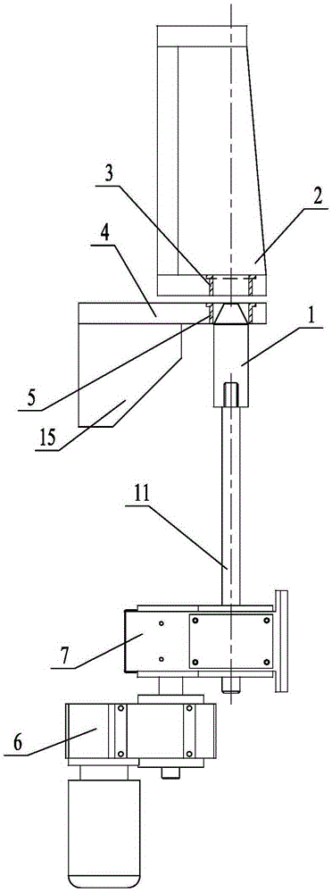
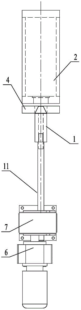
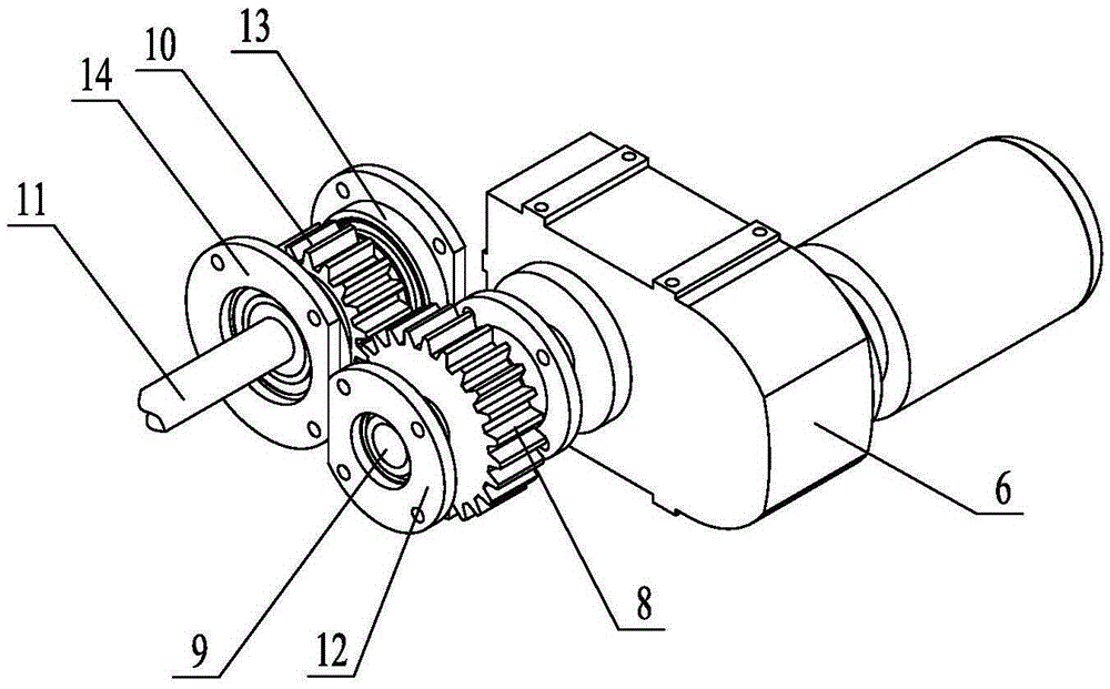
[0013] As shown in the figure; the positioning and locking device for the tapping machine in the embodiment mainly consists of a stop pin 1, an upper positioning seat 2, an upper positioning sleeve 3, a lower positioning seat 4, a lower positioning sleeve 5, a motor reducer 6, a housing 7, Pinion 8, pinion shaft 9, pull rod nut gear 10, pull rod 11, small bearing cap 12, pull rod nut 13, pull rod bearing cap 14 and reinforcing plate 15 etc. are formed.

[0014] Such as figure 1 , figure 2 As shown, the upper positioning sleeve 3 is set in the upper positioning seat 2, the lower positioning sleeve 5 is set in the lower positioning seat 4, the stop pin 1 is connected with the telescopic drive mechanism, and the stop pin 1 can be driven by the telescopic drive mechanism. Move back and forth; when the stop pin 1 passes through the upper positioning slee...


PUM


Abstract

The invention relates to a positioning locking device for a steel discharging machine. The positioning locking device comprises a stop pin, an upper positioning seat and a lower positioning seat and is characterized in that a pinion and a pull rod nut gear in a telescopic driving mechanism are arranged in a shell in parallel and in a side-by-side manner, and the pinion is in engagement transmission with the pull rod nut gear; a pinion shaft is mounted in the center of the pinion, the two ends of the pinion shaft are respectively mounted in two small bearing caps through a bearing support, the two small bearing caps are respectively fixedly mounted on the shell, and the shaft extension end of the pinion shaft is connected with an output shaft of a motor speed reducer; and a pull rod nut is fixedly mounted in the center of the pull rod nut gear, the two ends of the pull rod nut are respectively mounted in two pull rod bearing caps through the bearing support, the two pull rod bearing caps are respectively fixedly mounted on the shell, a threaded pull rod penetrates through the center of the pull rod nut, and the front end of the threaded pull rod is connected with the rear end of the stop pin. The structure is simple, compact and reasonable, positioning conveyed steel blanks can be carried out, the smooth discharging of the steel blanks is ensured, and the work efficiency is improved.

Description

technical field [0001] The invention relates to a positioning locking device, in particular to a positioning locking device for a tapping machine, which belongs to the technical field of metal processing equipment. Background technique [0002] In the field of metal processing, the tapping machine is located on the tapping side of the heating furnace. The hot steel billet that has been heated to the tapping temperature in the heating furnace is taken out through the tapping machine and placed on the tapping roller smoothly so as to be sent to the rolling machine and other metals. The next process is processed on the rolling equipment. [0003] When the traditional tapping machine is working, there is no positioning device to locate the conveyed steel billet, and problems such as inaccurate discharging position are prone to occur during the discharging process, which affects normal production work. Later, although a positioning device driven by a cylinder or an electric push...

Claims


Application Information

Patent Timeline
Patent Type & Authority Applications(China)
IPC IPC(8): C21D9/70
Inventor 赵军
Owner 无锡晶瑜智能机械有限公司
Why Eureka
Try Eureka