Turbine steam seal clearance adjustment method

A technology of steam seal clearance and adjustment method, which is applied in the direction of mechanical equipment, engine components, machines/engines, etc. It can solve the problems of complicated process, inability to measure, and burrs on the back arc of the steam seal, so as to achieve simple process, convenient operation, and ensure The effect of accuracy

Inactive Publication Date: 2016-02-10
HUADIAN ELECTRIC POWER SCI INST CO LTD
View PDF4 Cites 10 Cited by
  • Summary
  • Abstract
  • Description
  • Claims
  • Application Information

AI Technical Summary

Problems solved by technology

Including personnel factors (enlarge the gap to ensure safety, incorrect adjustment operation), equipment factors (poor elasticity of the spring leaf, loose adjustment block, burrs on the back arc of the steam seal), process factors (too large or too small gaps cannot be measured, relying on experience Estimated, cannot be quantified), leading to unsuccessful adjustment of the seal clearance
[0004] There are also some relatively good steam turbine seal clearance adjustment methods. For example, in the Chinese patent whose publication date is October 12, 2011 and whose publication number is CN102213110A, a method for measuring and trimming the radial clearance of the steam turbine seal is disclosed. Methods Quantitatively measure the seal gap of the whole circle with the seal gap measuring ruler, and read out the actual gap value for purposeful and targeted repair and scraping.

Method used


Image

  • Turbine steam seal clearance adjustment method
  • Turbine steam seal clearance adjustment method
  • Turbine steam seal clearance adjustment method

Examples


Embodiment Construction

[0028] The present invention will be further described in detail below with reference to the drawings and embodiments. The following embodiments are for explaining the present invention and the present invention is not limited to the following embodiments.

[0029] Examples.

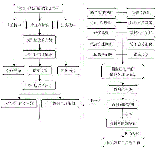
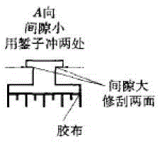
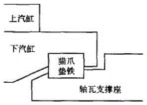
[0030] See Figure 1 to Figure 6 The method for adjusting the gap of the steam turbine seal in this embodiment adopts the method of pressing the lead wire in equal divisions on the circumference. The gap between the lower half of the cylinder and the horizontal joint surface is measured by a feeler gauge, and the gap of the other parts of the steam seal is glued to the corresponding specifications of the lead wire. Put it on the steam seal tooth, the end is fixed, hoist the rotor in the working position, the lead wire stuck on the steam seal tooth is pressed out a groove mark, hang out the rotor, and measure the remaining lead wire groove mark with the seal gap measurement ruler Part of the thickness, this t...


PUM


Abstract

The invention relates to a turbine steam seal clearance adjustment method. The turbine steam seal clearance adjustment method which is simple in process, convenient to operate and capable of digitally, accurately and truly quantifying the steam seal clearance adjustment quantity is not available at present. The turbine steam seal clearance adjustment method is characterized in that by the adoption of the mode that lead wires are pressed in a circumferential uniform division manner, a clearance, at a horizontal junction surface position, of a lower half cylinder sleeve is measured through a feeler gauge; as for steam seal clearances of other portions, the lead wires of corresponding specifications are pasted to steam seal teeth, ends are fixed, a rotor is hoisted to a working position, the lead wires pasted to the steam seal teeth are each rolled to form a groove mark, and the rotor is hoisted out; the thickness of the remaining portion of the groove mark of each lead wire is measured through a steam seal clearance measuring scale, the thicknesses are actual values of the steam seal clearances, the actual values are compared with design values, and adjustment values of the steam seal clearances are worked out; and then the turbine steam seal clearances are adjusted according to the adjustment values. The turbine steam seal clearance adjustment method is simple in process, convenient to operate and capable of accurately and digitally quantifying the steam seal clearance adjustment quantity.

Description

Technical field [0001] The invention relates to a method for adjusting the gap of the steam seal of a steam turbine, which is suitable for the installation and maintenance of various types of steam turbine units of thermal power, gas and nuclear power, and is mainly used for fine adjustment of the radial gap of the steam seal of the steam turbine. Background technique [0002] The adjustment of the gap of the steam seal is a very important and meticulous work in the process of steam turbine installation and maintenance, which is very important to the safe and economic operation of the unit. If the seal gap is too small, the rotor is easy to wear. If the seal gap is too large, the leakage of steam will increase, reducing the internal efficiency of the steam turbine. At the same time, the high and medium pressure cylinder steam will leak from the shaft end and affect the quality of lubricating oil, and the low pressure cylinder shaft end will leak air to reduce the unit vacuum. [0...

Claims


Application Information

Patent Timeline
IPC IPC(8): F01D11/00
Inventor 郑宏伟徐厚达罗海华田文俊李炜陈浩王彬孙宇
Owner HUADIAN ELECTRIC POWER SCI INST CO LTD
Why Eureka
Try Eureka