
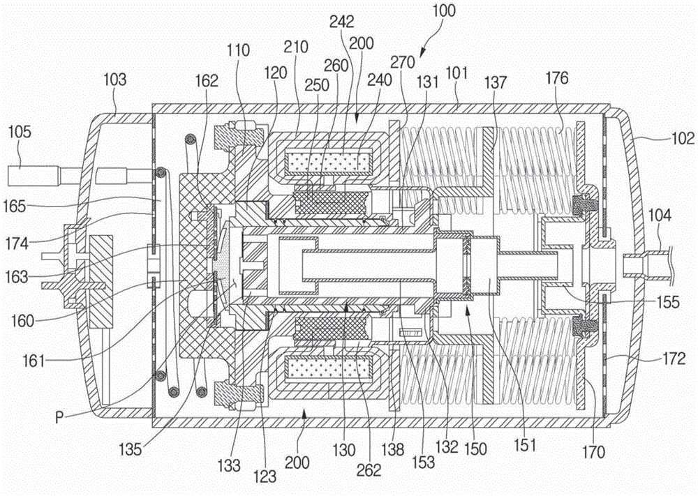
Linear compressor and linear motor

A linear motor and coil technology, applied in mechanical equipment, electromechanical devices, machines/engines, etc., can solve the problems of motor efficiency and output power drop, decrease, and increase of the slope of the motor force constant

Inactive Publication Date: 2016-02-10
LG ELECTRONICS INC
View PDF11 Cites 8 Cited by
  • Summary
  • Abstract
  • Description
  • Claims
  • Application Information

AI Technical Summary

Problems solved by technology

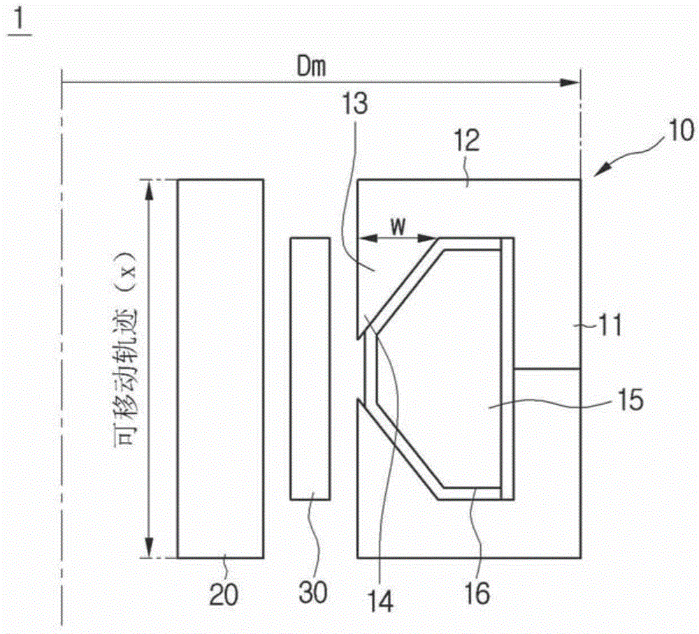
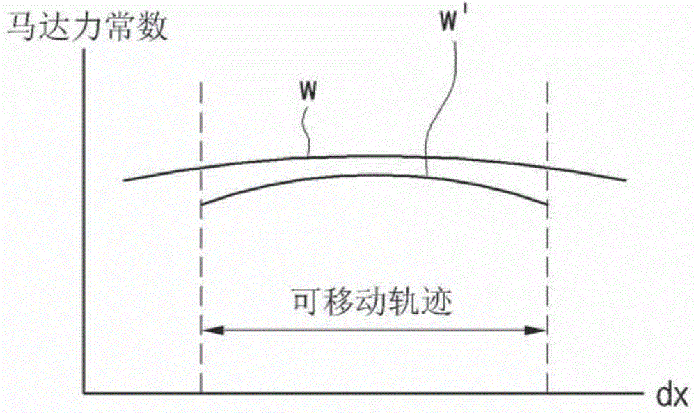
[0015] Furthermore, the motor force constant at the outer end of the plurality of magnetic poles 13 (the end of each magnetic pole adjacent to the second core 12 ) drops sharply, and the gradient of the motor force constant increases accordingly, which may cause Decrease in motor efficiency and output power

Method used


Image

  • Linear compressor and linear motor
  • Linear compressor and linear motor
  • Linear compressor and linear motor

Examples


Embodiment Construction

[0028] Hereinafter, some embodiments of the present invention will be described through exemplary drawings.

[0029] In the following detailed description of the preferred embodiments, reference is made to the accompanying drawings which form a part hereof, and show by way of illustration specific preferred embodiments. These embodiments are described in sufficient detail to enable those skilled in the art to practice the invention, and it is understood that other embodiments may also be utilized. In addition, logical structural, mechanical, electrical, and chemical changes may be made without departing from the spirit or scope of the invention. In order to avoid detail not necessary to enable those skilled in the art to practice the invention, the description may omit certain information known to those skilled in the art. The following detailed description should not be considered as limiting.

[0030] In addition, terms such as first, second, A, B, (a), (b) are used when d...


PUM


Abstract

The invention provides a linear compressor and a linear motor. The linear motor includes a first stator, a second stator spaced apart from the first stator; and a permanent magnet disposed to be movable in a first direction between the first and second stators. The first stator includes a bobbin with a coil wound thereon, and a stator core surrounding the bobbin. The stator core is located between the second stator and the coil and includes first and second magnetic poles spaced apart from each other. One portion or entire portions of each of the first and second magnetic poles have a constant magnetic path width within a range of a movement trajectory of the permanent magnet.

Description

technical field [0001] The invention relates to a linear compressor and a linear motor. Background technique [0002] Generally speaking, a compressor (Compressor) is a mechanical device that receives power from a power generating device such as an electric motor or a turbine and compresses air or refrigerant or other various working gases to increase the pressure. It is widely used in refrigerators and air conditioners. Classes of home appliances or entire industries. [0003] If this kind of compressor is classified, it can be divided into: a compression space for sucking and discharging working gas is formed between the piston (Piston) and the cylinder (Cylinder), and the piston performs linear reciprocating motion inside the cylinder while A reciprocating compressor (Reciprocating compressor) that compresses the refrigerant; a compression space for sucking and discharging working gas is formed between the eccentrically rotating roller (Roller) and the cylinder, and the ...

Claims


Application Information

Patent Timeline
Patent Type & Authority Applications(China)
IPC IPC(8): F04B35/04H02K16/04
CPCF04B35/045F04B39/122H02K1/145H02K33/00H02K33/12H02K2213/03
Inventor 洪彦杓郑圆铉卞正郁
Owner LG ELECTRONICS INC
Learn More