
Compound cooling ventilator with interior self-adaption cooling circulation

A cooling cycle, self-adaptive technology, used in mechanical equipment, machines/engines, liquid fuel engines, etc., can solve the problems of easy generation of condensed water, uneven heating and cooling of motors, unfavorable motors, etc., to reduce noise, low noise, The effect of condensed structure

Inactive Publication Date: 2016-02-10
CRRC DALIAN INST CO LTD
View PDF5 Cites 5 Cited by
  • Summary
  • Abstract
  • Description
  • Claims
  • Application Information

AI Technical Summary

Problems solved by technology

The disadvantages brought about by this are: 1) The inner air cylinder is too short, which will cause the rear guide vanes connecting the inner and outer air cylinders to be too short, thus affecting the strength of the air cylinder
It is even more unfavorable for aluminum alloy air ducts with lightweight requirements
2) If the air duct is too short, the distance between the rear guide vane and the impeller will be closer, resulting in increased noise
3) As part of the motor is exposed in the flow channel, it will cause uneven cooling and heat between the exposed part and the wrapped part of the motor, and condensed water is easy to generate, which is not good for the motor
If a motor without a self-cooling fan with a shortened inner air tube is used, the noise of the fan and the structural strength will be difficult to meet the requirements

Method used


Image

  • Compound cooling ventilator with interior self-adaption cooling circulation
  • Compound cooling ventilator with interior self-adaption cooling circulation

Examples


Embodiment Construction

[0012] The present invention will be further described below in conjunction with accompanying drawing.

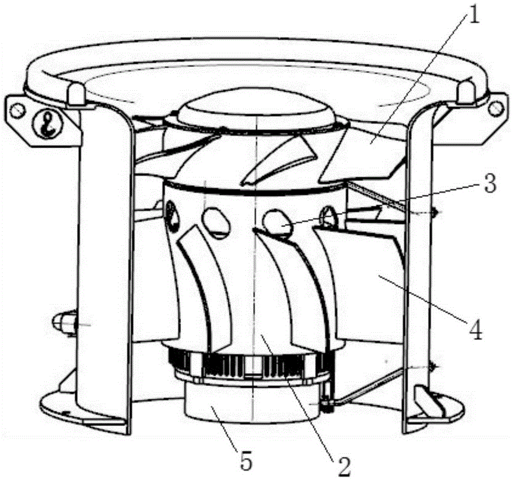
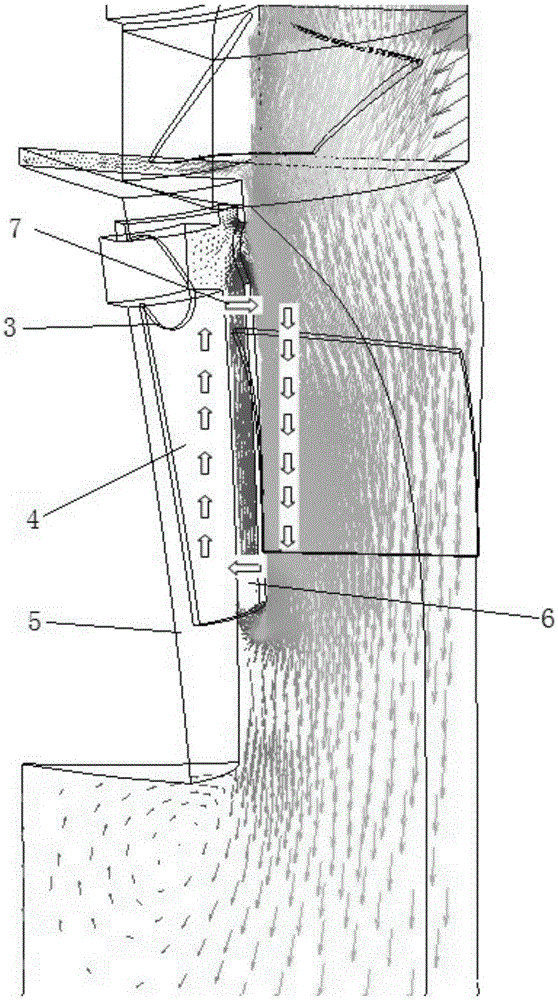
[0013] In the recooling ventilator with internal self-adaptive cooling cycle of the present invention, the front end of the motor 5 is equipped with an impeller 1, the motor 5 is covered with an inner air cylinder 2, and the inner air cylinder 2 is located behind the impeller 1 and maintains a gap. There is a rear guide vane 4, which is characterized in that: the front of the rear guide vane 4 on the inner air cylinder 2 is provided with a cooling ring, the cooling ring includes a group of cooling holes 3, and each rear guide vane 4 is provided with a cooling hole 3 in front, cooling The hole 3 is in the shape of a long hole, and its length direction is consistent with the inlet airflow angle of the rear guide vane 4 . Such as figure 1 As shown, in order to meet the requirements of the new generation of electric locomotives for the recooling fan with light weight, compact ...


PUM


Abstract

The invention discloses a compound cooling ventilator with an interior self-adaption cooling circulation. According to the compound cooling ventilator, an impeller is arranged at the front end of a motor; an inner air duct sleeves the motor; the inner air duct is located behind the impeller and a clearance is reserved between the inner air duct and the impeller; rear guide vanes are arranged outside the inner air duct; a cooling ring is arranged in front of the rear guide vanes on the inner air duct; the cooling ring comprises a group of cooling holes; a cooling hole is formed in front of each rear guide vane; the cooling holes are strip-shaped; the length direction of each cooling hole is consistent with the airflow angle of the inlet of the corresponding rear guide vane; and the distance between each rear guide vane and the impeller is smaller than or equal to one time of the chord length of the root part of fan blades. Even for a new-generation electric locomotive with the speed of 200 kilometers per hour, the requirements of light weight, compact structure and low noise can still be met.

Description

technical field [0001] The invention relates to the field of fluid machinery, in particular to a recooling ventilator with an internal self-adaptive cooling cycle. Background technique [0002] The recooling fan is a fan used for cooling the traction transformer and traction converter of an electric locomotive, and is usually installed on the transition air duct of the compound cooling radiator. The recooling fan sucks in air from the roof or the side, and the air discharged axially passes through the transition air duct and blows to the radiator, taking away the heat generated by the traction transformer and traction converter. Due to the limitation of the axial space size of the car body, the axial size of the axial flow fan is generally relatively short. If a motor with its own cooling fan is used, the motor will inevitably protrude outside the fan duct and extend into the transitional air duct. Since the air outlet of the axial flow fan is a circular air outlet, the clo...

Claims


Application Information

Patent Timeline
Patent Type & Authority Applications(China)
IPC IPC(8): F04D25/08F04D29/58F04D29/66F04D29/54
Inventor 李瑜王润乔巍
Owner CRRC DALIAN INST CO LTD
Learn More