
Atomizer, combustion device including atomizer, and gas turbine plant

A technology of spray nozzles and gas turbines, which is applied in the direction of combustion equipment, gas turbine devices, mechanical equipment, etc. It can solve the problems of shortened mixing time of the flow channel, easy wear of the wall surface, and insufficient mixing, so as to promote micronization and inhibit wear. Effect

Active Publication Date: 2016-02-10
MITSUBISHI POWER LTD
View PDF10 Cites 4 Cited by
  • Summary
  • Abstract
  • Description
  • Claims
  • Application Information

AI Technical Summary

Problems solved by technology

However, since the mixed fluid flows at a high speed, the mixing time in the flow channel is shortened, and there is a common problem that the mixing cannot be performed sufficiently.
In addition, in the mixing part, since the flow path of the spray fluid connected to the upstream side intersects the flow path of the spray medium, the wall surface is easily worn due to the collision of the solid content in the spray fluid with the wall surface of the internal mixing chamber. subject

Method used


Image

  • Atomizer, combustion device including atomizer, and gas turbine plant
  • Atomizer, combustion device including atomizer, and gas turbine plant
  • Atomizer, combustion device including atomizer, and gas turbine plant

Examples


Embodiment 1

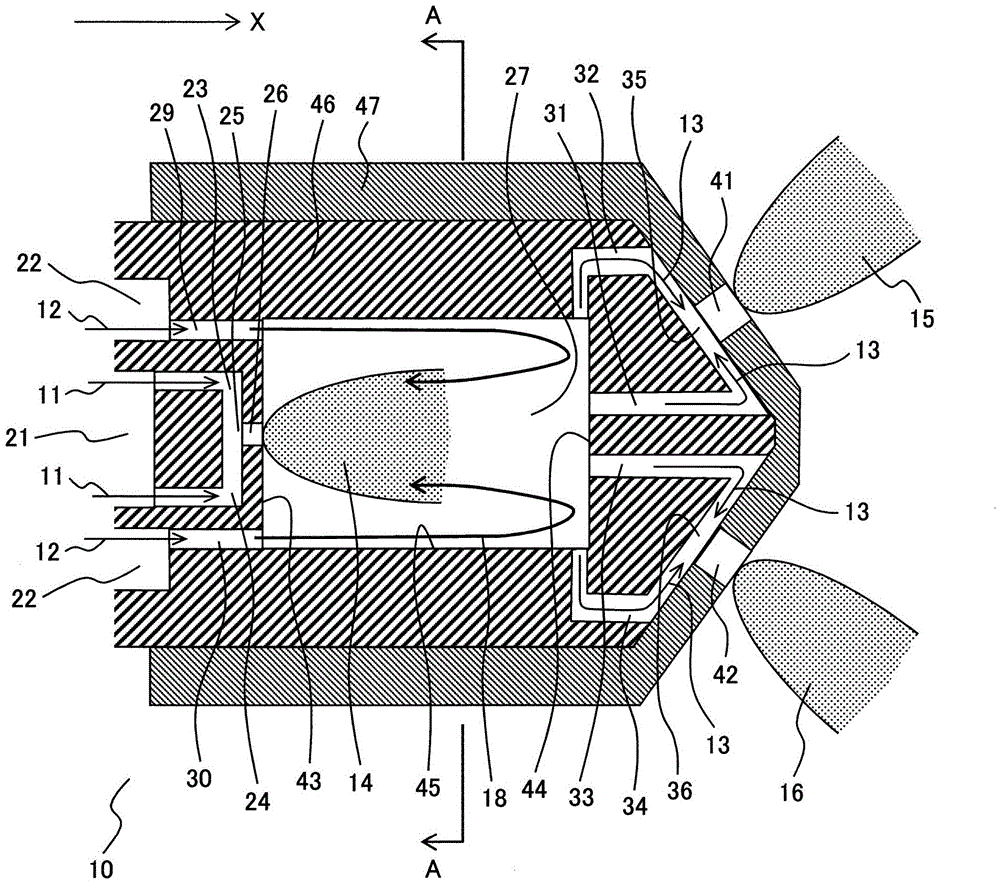
[0035] use Figure 1 to Figure 8 The spray nozzle 10 of the first embodiment of the present invention will be described.

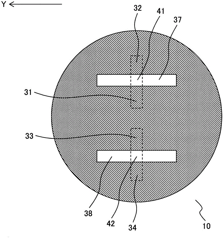
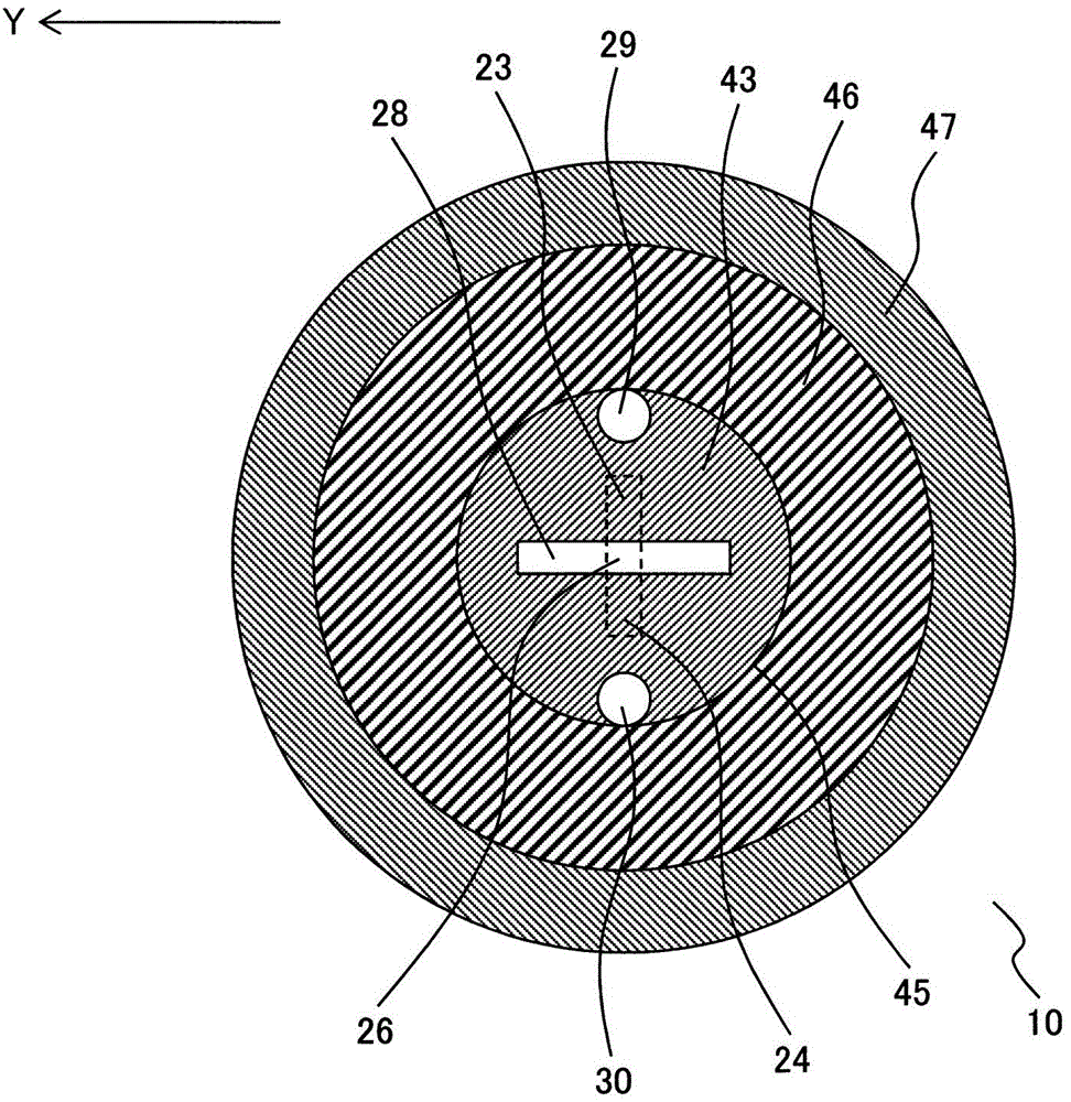
[0036] figure 1 It is a sectional view along the axial direction (X direction) of the tip portion of the spray nozzle 10 of this embodiment. exist figure 1 Among them, the X direction is the axial direction of the spray nozzle 10 and is the supply direction of the spray fluid. figure 2 It is viewed from the downstream side of the supply direction of the spray fluid 11 figure 1 Front view of the spray nozzle 10. image 3 yes figure 1 The cross-sectional view of the spray nozzle 10 on the cutting line A-A is a cross-sectional view of the spray nozzle 10 viewed from the downstream side in the supply direction of the spray fluid at the position of the internal mixing chamber 27 of the spray nozzle 10 . exist figure 2 , 3 , the Y direction is the radial direction of the spray nozzle 10 .

[0037] in addition, Figure 4 It is a cross-sectional view a...

Embodiment 2

[0097] use Figures 9 to 11 The spray nozzle 50 of the second embodiment of the present invention will be described.

[0098] Figure 9 It is a sectional view along the axial direction (X direction) of the tip portion of the spray nozzle 50 of this embodiment. exist Figure 9 In , the X direction is the axial direction of the spray nozzle 50 and is the supply direction of the spray fluid. Figure 10 Viewed from the downstream side of the spray fluid supply direction Figure 9 Front view of the spray nozzle 50. Figure 10 Viewed from the downstream side of the spray fluid supply direction Figure 9 Front view of the spray nozzle 50. Figure 11 yes Figure 9 A cross-sectional view of spray nozzle 50 cut along line A-A. It is a cross-sectional view of the spray nozzle 50 viewed from the downstream side in the supply direction of the spray fluid at the position of the internal mixing chamber 27 of the spray nozzle 50 . exist Figure 10 , Figure 11 , the Y direction is ...

Embodiment 3

[0121] use Figure 12 A combustion device including a spray nozzle according to an embodiment of the present invention will be described. In this embodiment, a gas turbine combustor is exemplified as a combustion device including a spray nozzle. In this embodiment, the gas turbine combustor is provided with the spray nozzle 10 shown in the first embodiment, but may be provided with the spray nozzle 50 shown in the second embodiment.

[0122] Figure 12 It is a schematic diagram showing the overall structure of a gas turbine facility provided with a gas turbine combustor 67 according to this embodiment. Figure 12The gas turbine plant shown includes a compressor 66 , a gas turbine combustor 67 , a turbine 68 and a generator 69 . The compressor 66 compresses the air to generate high-pressure combustion air 61 , and supplies it to the gas turbine combustor 67 . The gas turbine combustor 67 is a combustion device that introduces combustion air 61 and fuel 62 (liquid fuel), bur...


PUM


Abstract

The invention provides an atomizer capable of promoting microparticulation of a spray fluid and inhibiting abrasion caused by a solid component of the spray fluid and a combustion device including the atomizer. The atomizer includes a mixing chamber (27), spray fluid flow passages (23, 24) supplying a spray fluid (11) to the mixing chamber (27), a spray medium flow passage (29, 30) supplying a spray medium (12) to the mixing chamber, outlet holes (41) spraying a fluid mixture (13) of the spray fluid and the spray medium, and fluid mixture flow passages (31, 32) connecting the mixing chamber (27) and the outlet holes (41) to each other. The fluid mixture flowing through each of the fluid mixture flow passages joins with each other at a joining section (35) and is sprayed from the outlet hole. The mixing chamber (27) includes a middle ejection hole (26) spraying the spray fluid to the mixing chamber. The middle ejection hole is arranged at a joining section of the spray fluid flow passages. The spray fluid flowing through the spray fluid flow passages joins with each other at the joining section and is sprayed from the middle ejection hole.

Description

technical field [0001] The present invention relates to a spray nozzle and a combustion device equipped with the spray nozzle, and more particularly, to a two-fluid spray type spray nozzle for atomizing liquid fuel (spray fluid) using gas (spray medium), and a combustion device provided with the spray nozzle. Background technique [0002] In combustion devices such as gas turbine combustors, both diversification of fuels that can handle various fuels and improvement of environmental performance are required. [0003] With regard to diversification of fuels, some gas turbines use so-called dual-fuel burners that use liquid fuels such as light oil or A-heavy oil in addition to fuel gas represented by natural gas, depending on the fuel supply status. . In this combustor, both gaseous fuel and liquid fuel can be used, so even if the fuel supply situation changes, the operation can be continued. [0004] Compared with the improvement of the environmental performance of the gas ...

Claims


Application Information

Patent Timeline
Patent Type & Authority Applications(China)
IPC IPC(8): F23R3/12F23R3/28
CPCF23R3/28F23D11/102F23D11/38F02C7/22F23R3/286F02C3/30F23R3/30F02C7/222
Inventor 冈崎洋文折井明仁
Owner MITSUBISHI POWER LTD
Learn More