A scanning method to realize high-resolution and large-field cl imaging of plate-shaped samples

A scanning method and high-resolution technology, which is applied in the field of scanning to realize high-resolution and large-field CL imaging of plate-shaped samples, and can solve problems such as inability to perform tomographic scanning, no solution proposed, thin thickness, etc.

Active Publication Date: 2019-06-07
锐影检测科技济南有限公司
View PDF7 Cites 0 Cited by
  • Summary
  • Abstract
  • Description
  • Claims
  • Application Information

AI Technical Summary

Problems solved by technology

Although the method proposed above solves the large-field-of-view imaging problem of some long and large objects to a certain extent, it is not suitable for both long and wide objects, that is, large plate-shaped objects with large length and width scales and thin thickness. suggest solution
[0004] In practical applications, many flat-shaped objects, such as multi-layer printed circuit boards, honeycomb adhesive panels on aerospace vehicles, solar panels, plate-shaped fossils, etc., due to their large length and width scales and thin thickness, are used in Tomography cannot be performed in conventional industrial CT because X-rays may not penetrate the sample along the long axis

Method used


Image

  • A scanning method to realize high-resolution and large-field cl imaging of plate-shaped samples
  • A scanning method to realize high-resolution and large-field cl imaging of plate-shaped samples
  • A scanning method to realize high-resolution and large-field cl imaging of plate-shaped samples

Examples


specific Embodiment 1

[0058] Specific embodiment 1: A mold body for simulating the soldering of a chip on a substrate and detecting soldering bubbles.

[0059] According to the parameters in Table 2, the design Figure 15 The phantom reflected in the front view of middle a and the side view of b is a sample in which the simulated chip is soldered on the substrate and there are bubbles in the soldering layer. The cuboid 1 represents the substrate, the cuboids 2 and 3 represent the chips, the cuboids 4 and 5 represent the soldering layer, and the cylinders represent the air bubbles in the soldering layer.

[0060] Table 2

[0061]

[0062]

[0063] Under low magnification conditions, the whole sample is tomographically imaged, and the results are as follows Figure 16 As shown, the air bubbles in the visible sample are blurred. Under the condition of high magnification ratio, the sample is scanned in 2*4 blocks, "square" splicing, the result is as follows Figure 17 As shown in the figure, ...

specific Embodiment 2

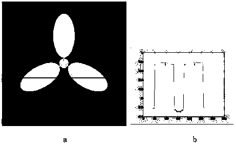
[0064] Specific embodiment 2: simulate the sample of three-blade paddle, carry out " honeycomb " splicing

[0065] According to the parameters in Table 1, the design Figure 12 The "three-blade paddle" shaped phantom is shown. The phantom consists of cylinders and ellipsoids. Among them, ellipsoids 1, 2, and 3 constitute the main parts of the three-bladed paddle sample, balls 4, 5, and 6 represent defects such as air bubbles in the sample, and spheres 7 and 8 represent defects such as cracks in the sample.

[0066] Table 1

[0067]

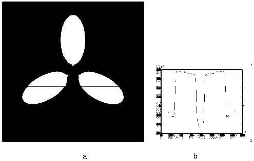
[0068] Under low magnification conditions, the entire sample is imaged to obtain a tomogram of the sample. Take the tomographic image of the middle layer ( Figure 13 a) Observation, it can be seen that under low magnification conditions, although the whole sample can be tomographically imaged, the defects in the sample cannot be clearly displayed. Take a row of data display ( Figure 13 b), the contrast of the visible defect part is smal...


PUM


Abstract

The invention provides a scanning method for achieving high-resolution large-view-field CL imaging of plate-shaped samples. The method includes the steps that parameters are input, the number and the mode of spliced subimages are adjusted and determined, data are collected and spliced, and results are output. Projection data are collected through segmented scanning of the plate-shaped samples under the high-amplification-ratio condition, and high-resolution large-view-field faulted images of the large-area plate-shaped samples are finally obtained through the image splicing method in a square field-character-shaped or hexagonal honeycomb-shaped mode.

Description

technical field [0001] The invention relates to an X-ray computerized laminography (computed laminography) technology, especially a method for performing high-resolution and large-field tomographic imaging on plate-shaped samples, which belongs to the realization of plate-shaped samples for X-ray CT imaging detection. A scanning approach for high-resolution large-field-of-view CL imaging. Background technique [0002] After more than half a century of development, computed tomography (CT-computed tomography) plays an important role in medical, industrial, security inspection and other fields. Since the detection object of medical CT is basically a human body or an organ, its morphological characteristics and density information have specific rules and ranges, and the detection accuracy only needs to meet the requirements of medical diagnosis accuracy. However, because radiation is harmful to the human body, the current medical CT mainly One of the research directions is how...

Claims


Application Information

Patent Timeline
Patent Type & Authority Patents(China)
IPC IPC(8): G01N23/046
Inventor 王雅霄魏存峰刘宝东舒岩峰阙介民王燕芳孟凡辉周俊光袁路路邵雨濛王哲李卓昕申善威魏龙
Owner 锐影检测科技济南有限公司
Why Eureka
Try Eureka