Optical projection system

A technology of optical projection and projection system, applied in the field of optical projection system, can solve the problems of optical machine position deviation, unfavorable large-scale mass production, high experience requirements, etc., to achieve the effect of avoiding deviation and conducive to large-scale production

Inactive Publication Date: 2016-02-10
马国光
View PDF5 Cites 3 Cited by
  • Summary
  • Abstract
  • Description
  • Claims
  • Application Information

AI Technical Summary

Problems solved by technology

[0003] In the DLP display unit, there is a deviation between the installation position of the optical machine and the housing, which leads to the situation that the graphics cannot be accurately displayed on the screen. The traditional solution is to adjust the six axes of the reinforced optical machine and fine-tune the distance and left an

Method used


Image

  • Optical projection system
  • Optical projection system
  • Optical projection system

Examples


Embodiment Construction

[0015] The present invention will be further described below in conjunction with the accompanying drawings.

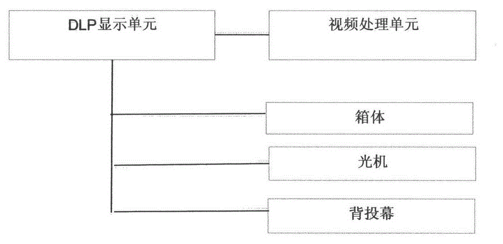
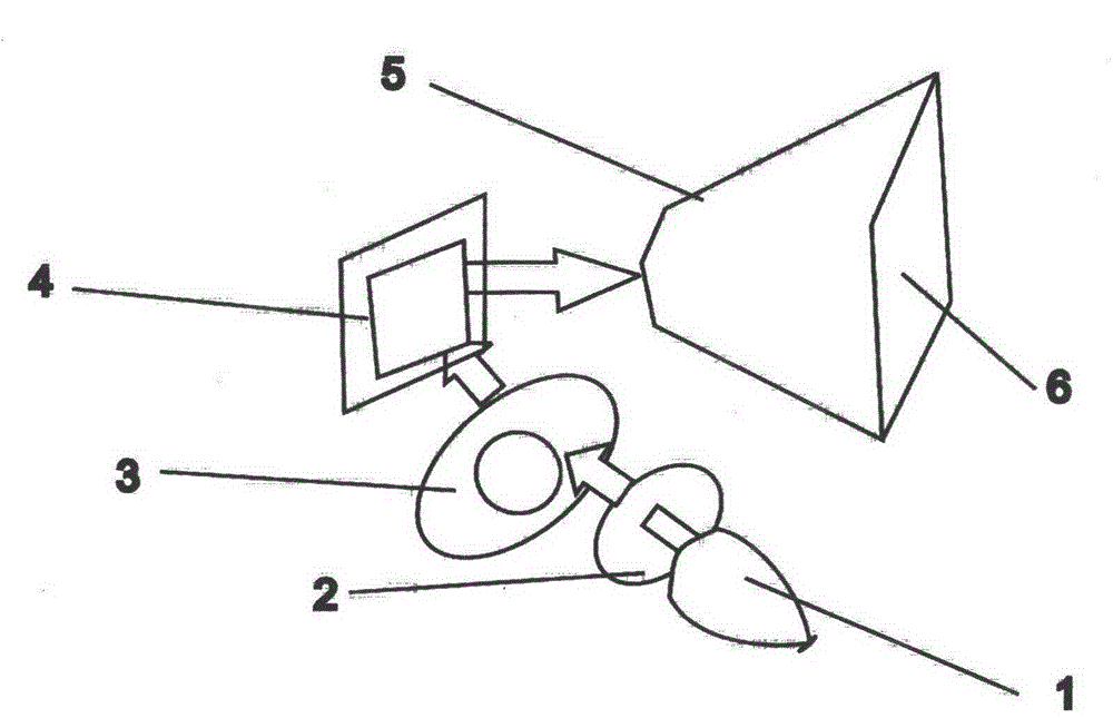
[0016] Such as figure 1 with 2 As shown, the embodiment optical projection system includes a DLP display unit and a video processing unit, and the DLP display unit includes a cabinet, an optical machine and a rear projection screen, and the optical machine reflects the display light to the rear projection screen through a mirror reflection On the screen, the viewer can watch the image in front of the rear projection screen. The box is used to accommodate various components of the DLP display unit. The optical machine includes a bulb 1 , a filter 2 , a color wheel 3 , a DMD (Digital Micromirror Device: digital microlens device) chip 4 and a lens 5 . The light emitted by the light bulb 1 is filtered by the filter mirror 2 and projected onto the color wheel 3 , and the color wheel 3 separates and processes colors through high-speed rotation. The light separated by the...


PUM


Abstract

The present invention relates to an optical projection system which comprises DLP display units and a video processing unit. Each of the DLP display units comprises a box body, an optical machine and a rear projection screen. The optical machine comprises a lens. The light which goes through the optical machine is projected to the rear projection screen through a lens. The video processing unit comprises a bottom plate and a core plate. The bottom plate comprises a video access end and a connection device. The video access end receives a video image signal. The core plate comprises a signal interface and a memory. The connection device is connected to the bottom plate and the core plate respectively. The signal interface is connected to the optical machine. The memory is used for storing a correction parameter after a video image is corrected. Through storing the parameter of the geometrically adjusted video image into the core plate, the six-axis adjustment of each of the DLP display units in the production process is not needed, and the large-scale production is facilitated. At the same time, the bias generated in the condition that a later six-axis is influenced by gravity and external force is avoided.

Description

technical field [0001] The invention relates to an optical projection system, in particular to a DLP projection system. Background technique [0002] DLP is the abbreviation of "Digital Light Procession", that is, digital light processing, which means that this technology first processes the image signal digitally, and then projects the light. DLP technology is an original solution for producing digital multi-light source displays using optical semiconductors. It is an all-digital display technology with high reliability, which can provide the best image effect in various products such as large-screen digital TV, company / home / professional conference projector and digital camera (DLPCinema). At the same time, this solution is also a fully mature independent technology adopted by many electronics companies around the world. [0003] In the DLP display unit, there is a deviation between the installation position of the optical machine and the housing, which leads to the situa...

Claims


Application Information

Patent Timeline
IPC IPC(8): G03B21/14H04N9/31
Inventor 马国光
Owner 马国光
Why Eureka
Try Eureka