

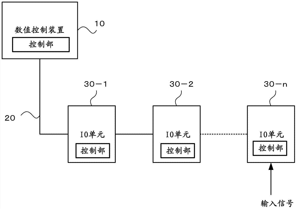
Numerical control system
A technology of numerical control and numerical control devices, applied in the general control system, control/regulation system, digital control, etc., can solve the problems of increased circuit scale and disadvantages, and achieve the effect of shortening the cycle time
- Summary
- Abstract
- Description
- Claims
- Application Information
AI Technical Summary
Problems solved by technology
Method used
Image

Examples
Embodiment approach 1
[0034] Embodiment 1 is a method of "changing the idle signal to a specific signal pattern and then notifying the numerical control device".
[0035] The numerical control system of the present invention changes the idle signal output from the IO unit 30 to a specific signal pattern when the IO unit detects the input of the touch sensor output. Since the idle signal changing to a specific mode is input to the numerical controller 10, the numerical controller 10 having detected the specific mode can detect the input of the touch sensor output through the IO unit 30 without waiting for the communication of the DI / DO signal. Thereby, on the basis of not requiring mediation for data transmission, there is no delay time, and it is possible to communicate to the numerical controller 10 that there is an input of the contact sensor output in the IO unit 30, so that the measurement operation can be performed immediately after the in-machine measurement operation is completed. Starts the...
Embodiment approach 2
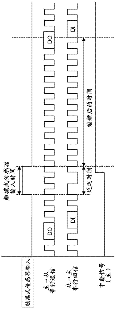
[0042] Embodiment 2 is a method of "notifying the numerical controller after changing the period of the idle signal".
[0043] As a method of changing the specific signal pattern of the idle signal, a method of notifying the input of the touch sensor output by changing the cycle of the idle signal will be described.
[0044] The IO unit 30 includes a control unit (first control unit) that changes the cycle of the idle signal when the IO unit 30 receives an output signal from the touch sensor. On the other hand, the numerical controller 10 includes a control unit (second control unit) that turns on the interrupt signal only when it detects that the cycle of the idle signal is changed. With this configuration, it is possible to accurately notify the numerical controller 10 of the input of the touch sensor output without increasing the delay time.
[0045] figure 2 It is a figure explaining the embodiment for changing the period of an idle signal. When the output signal of th...
Embodiment approach 3
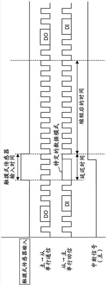
[0048] Embodiment 3 is a method of "mixing a specific data pattern into an idle signal and then notifying the numerical control device".
[0049] image 3 It is a diagram explaining an embodiment in which a data pattern is mixed into an idle signal. Explanation of touch sensor input time, delay time and shortened time is similar to Embodiment 2 figure 2 The instructions are the same.
[0050] Embodiment 3 is a mode in which a specific data pattern is mixed into an idle signal to notify that there is an input of a touch sensor output. When the IO unit 30 receives an output signal from the touch sensor, a control unit (first control unit) that mixes a specific data pattern into the idle signal is incorporated in the IO unit 30 . On the other hand, a control unit (second control unit) that turns on an interrupt signal only when a data pattern in which an idle signal is changed by a predetermined number of bits or more is detected is combined with the numerical controller 10 ....
PUM
 Abstract
Description
Claims
Application Information