Installation structure of sludge thickener

A technology of installation structure and thickener, applied in the direction of dewatering/drying/concentrated sludge treatment, etc., can solve the problems of easy clogging of pipelines, easy agglomeration, sludge floating, etc., so as to improve the concentration efficiency, reduce the drying rate, and discharge the sludge. Efficient effect

Inactive Publication Date: 2016-02-17
JIANGSU HUADA ENVIRONMENTAL ENG CO LTD
View PDF4 Cites 1 Cited by
  • Summary
  • Abstract
  • Description
  • Claims
  • Application Information

AI Technical Summary

Problems solved by technology

[0003] However, in the process of thickening the sludge in the sludge thickener, some sludge will float up, and it is easy to agglomerate under the conditions of sunlight and high temperature, and a thicker sludge solid layer is formed on the liquid surface of the thickening tank.
In the cutting-type sludge thickener of the prior art, when the sludge solids form into large pieces and sink, the bars cannot sufficiently break up the sludge solids through stirring, causing the large sludge to sink into the The sedimentation zone is then brought into the sludge discharge pipeline, which is easy to block the pipeline, seriously reducing the working quality and efficiency of the concentrator, and at the same time, it will also affect the desliming effect in the next treatment process.

Method used


Image

  • Installation structure of sludge thickener
  • Installation structure of sludge thickener

Examples


Embodiment 1

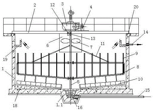
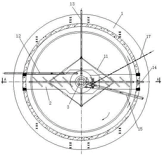
[0013] Embodiment 1: a kind of sludge thickener installation structure, comprises circular pool body 1, is installed in the sludge thickener in circular pool body 1, and circular pool body 1 top is provided with working bridge 2, and the center of working bridge 2 A vertical worm gear reducer 3 is installed, the reducer 3 is connected to the motor 4 through a pulley, the transmission shaft of the reducer 3 is connected to the stirring shaft 5, the upper end of the stirring shaft 5 is sleeved in the guide tube 6, and the stirring shaft located in the guide tube 6 5 is provided with a stirring blade 7, and the middle section of the stirring shaft 5 is provided with 4 U-shaped wall scraping pipes 8 connected with the stirring shaft 5 around the center of the stirring shaft 5. The upper end of the bottom pipe of the U-shaped wall scraping pipe 8 is arranged at intervals with vertical The upward grid bar 9, the lower end of the bottom pipe is connected with a mud scraper 10, the upp...


PUM


Abstract

An installation structure of a sludge thickener comprises a circular pool body and a sludge thickener body installed inside the circular pool body. A working bridge is arranged at the top end of the circular pool body. A vertical worm reducing gear is installed in the center of the working bridge. The reducing gear is connected with a motor through a belt wheel. A transmission shaft of the reducing gear is connected with a stirring shaft. The upper end of the stirring shaft is sleeved with a flow guiding cylinder. Stirring blades are arranged on the stirring shaft inside the flow guiding cylinder. Four U-shaped wall scraping pipelines communicated with the stirring shaft are arranged at the middle section of the stirring shaft around the circle center of the stirring shaft. Upward-vertical grid bars are distributed at the upper end of the bottom pipeline of the U-shaped wall scraping pipelines at intervals. The lower end of the bottom pipeline is connected with a scraper. The upper pipeline of the U-shaped wall scraping pipelines is provided with a pull rod to be fixed to the stirring shaft in a tensioning mode. A settling pond sludge discharging pipe and an oil-water separator sludge discharging pipe are connected to the flow guiding cylinder in the tangent direction. A supernate outlet pipe is formed in the portion, close to the top end, of the circular pool body. A sludge discharging pipe is formed in the bottom end of the circular pool body. The structure is reasonable, the sludge discharging efficiency is high, the stirring blades are arranged inside the flow guiding cylinder, the sludge block drying rate is greatly decreased, and the thickening efficiency is improved.

Description

technical field [0001] The invention relates to the field of sewage treatment, in particular to a sludge thickener. Background technique [0002] The cutting sludge thickener is a kind of center-driven continuous or intermittent thickening and clarification equipment. It is mainly aimed at sludge with a sludge concentration of 1% or less than 1%, increasing its solid content, that is, the sludge concentration. After being concentrated by a cutting-type sludge thickener, the outflow concentration is above 3%, which is convenient. Subsequent mechanical dehydration improves the working efficiency of mechanical dehydration. [0003] However, in the process of thickening the sludge in the sludge thickener, some sludge will float up, and it is easy to agglomerate under the conditions of sunlight and high temperature, and a thicker sludge solid layer is formed on the liquid surface of the thickening tank. In the cutting-type sludge thickener of the prior art, when the sludge soli...

Claims


Application Information

Patent Timeline
Patent Type & Authority Applications(China)
IPC IPC(8): C02F11/12
Inventor 曹云伟胡剑明许黎明赵法新叶永东李婷
Owner JIANGSU HUADA ENVIRONMENTAL ENG CO LTD
Why Eureka
Try Eureka