BIM-based (building information modeling based) internal cladding and external connecting beam or column
An external, combined beam technology, used in buildings, building structures, etc., can solve the problems of connection structure corrosion, poor mechanical strength, and high manufacturing costs, and achieve fast on-site construction speed, improved connection strength, and fast connection speed. Effect
- Summary
- Abstract
- Description
- Claims
- Application Information
AI Technical Summary
Problems solved by technology
Method used
Image

Examples
Embodiment 1
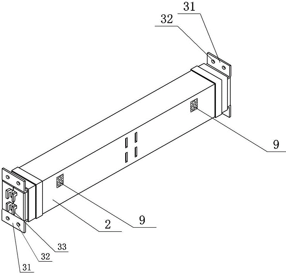
[0028] Example 1: A BIM-based beam (or column) with internal and external connections, see figure 1 and figure 2 , using thin-walled steel single beams and thin-walled steel single columns, and setting a single active connector and passive connection structure between the beams and columns. see image 3 , only a single active connector is provided at the end of the single beam 2, and only the hooking hole 4 is provided at the middle of the single column 1. see Figure 4 , while the single-type active connector is provided at the end of the single beam 2, a hooking hole 4 is provided at the middle of the single beam 2.
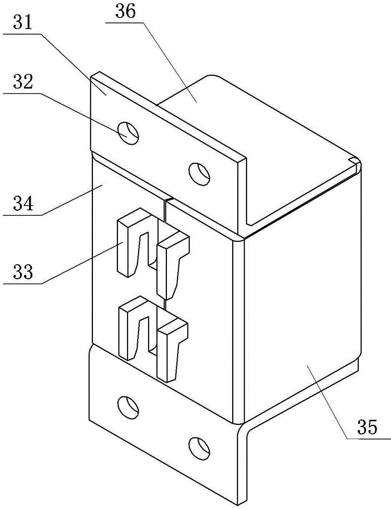
[0029] see Figure 5 and Figure 6 As shown, the active connector includes a front wall, a rear wall, two side walls, upper and lower walls, and connecting flanges 31 arranged on the upper and lower walls and n-shaped hooks 33 arranged on the front wall (hook support wall 34 ). In fact, the active connector described in this embodiment is a single active...
Embodiment 2
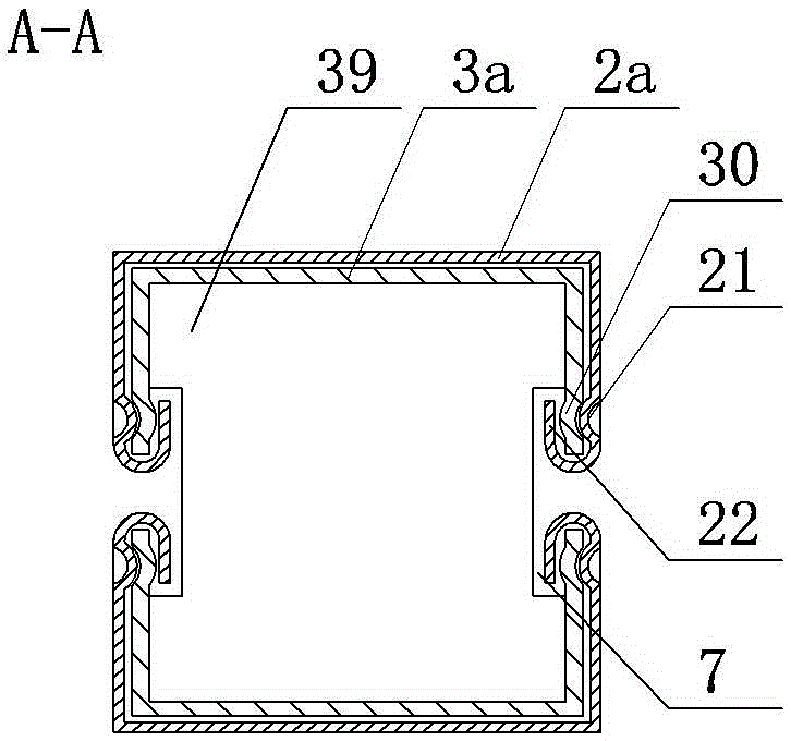
[0034] Embodiment 2: Based on Embodiment 1, the beams, columns and active connectors are respectively modified to form a C-shaped steel composite beam 2a, a C-shaped steel composite column 1a, a C-shaped steel composite active connector 3a and a C-shaped steel composite passive connector 5. see Figure 8-Figure 10 , the active connector is a C-shaped steel combined active connector welded by two paired C-shaped steels. The inner sides of the C-shaped steels of the two paired buckles match the welded web at least at the end position, and the outer surfaces of the C-shaped steels of the two paired buckles There are positioning grooves for stamping or punching; there are relief grooves that open outward between each web plate and the two side plates of the channel-shaped steel plate or the channel-shaped connecting plate; Tie positioning groove 51, the draw-in groove is arranged at the position corresponding to the web.
[0035] The beam or column is a thin-walled beam or column...
Embodiment 3
[0037] Embodiment 3: On the basis of Embodiment 1, change the steel structure beam or column into solid wood beam 2b, such as Figure 11 As shown, the active connectors are fitted over the ends of solid wood beams or columns and secured with steel ties.
PUM
 Abstract
Description
Claims
Application Information
 - R&D
- Intellectual Property
- Life Sciences
- Materials
- Tech Scout
- Unparalleled Data Quality
- Higher Quality Content
- 60% Fewer Hallucinations
Browse by: Latest US Patents, China's latest patents, Technical Efficacy Thesaurus, Application Domain, Technology Topic, Popular Technical Reports.
© 2025 PatSnap. All rights reserved.Legal|Privacy policy|Modern Slavery Act Transparency Statement|Sitemap|About US| Contact US: help@patsnap.com