Ultrasonic fatigue test vibration displacement monitoring device

A technology of fatigue test and vibration displacement, which is applied in the direction of measuring device, using optical device, and using sound wave/ultrasonic wave/infrasonic wave for material analysis, etc. It can solve the problems of inability to measure vibration displacement, unstable oscilloscope waveform, and unstable displacement value. Achieve the effect of strong repeatability, stable results and precise control

Inactive Publication Date: 2016-02-17
武汉钢铁有限公司
View PDF6 Cites 9 Cited by
  • Summary
  • Abstract
  • Description
  • Claims
  • Application Information

AI Technical Summary

Problems solved by technology

In addition, the eddy current sensor requires the measured body to be non-magnetic, and for metals with good magnetic permeability, such as nickel-based alloys, the vibration displacement cannot be measured
[0007] On the whole, when using the eddy current sensor to actually measure the vibration displacement of the ultrasonic fatigue test, it is found that the eddy current sensor is easily interfered by other electrical signals, resulting in unstable waveform of the oscilloscope, and more waveform noise, resulting in the final measured displacement value. stable, poor repeatability
In addition, eddy current sensors are not suitable for metals with good magnetic permeability, for example, they are not suitable for ultrasonic fatigue vibration displacement measurement of nickel-based alloys

Method used


Image

  • Ultrasonic fatigue test vibration displacement monitoring device
  • Ultrasonic fatigue test vibration displacement monitoring device
  • Ultrasonic fatigue test vibration displacement monitoring device

Examples


Embodiment Construction

[0027] Below in conjunction with accompanying drawing and implementation example, the present invention is specifically explained:

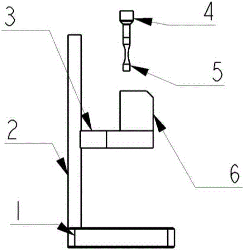
[0028] like figure 2 , 3 Shown is a preferred implementation example of the present invention, including a calibration platform, a laser displacement sensor, a controller and a computer.

[0029] The calibration table is composed of a base 1 , a back plate 2 and an arm 3 .

[0030] like figure 2 The shown base 1 is vertically connected to the backboard 2, and the support arm 3 is vertically connected to the backboard 2, parallel to the base 1, and the support arm 3 can move up and down along the backboard 2 to adjust its height.

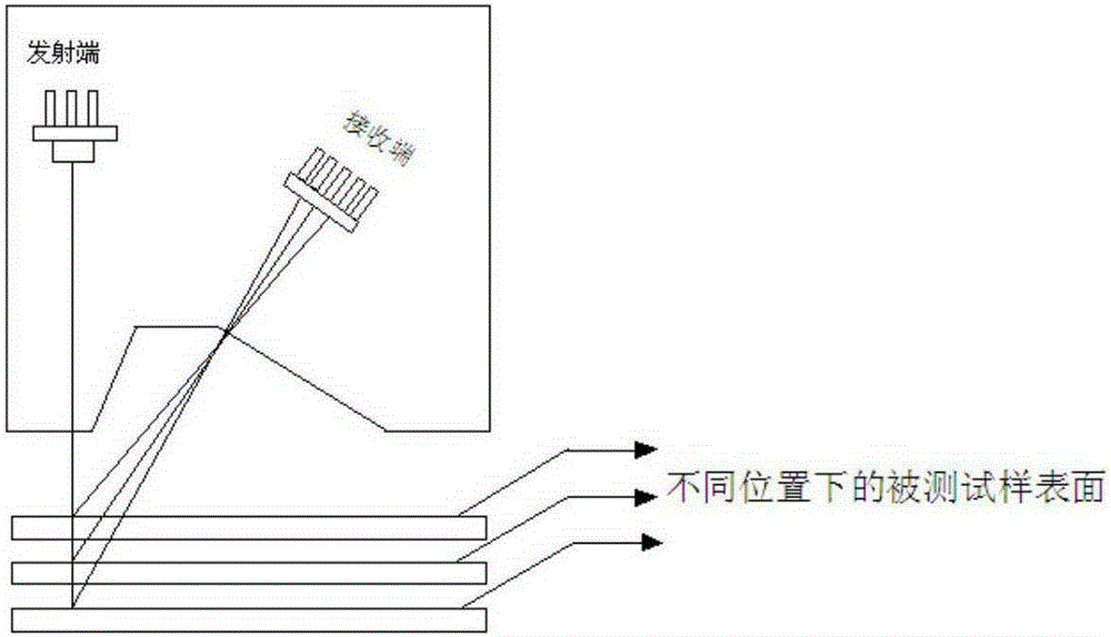
[0031] like figure 2 The laser sensor 6 shown is fixed on the support arm 3 and is located directly below the sample 5 .

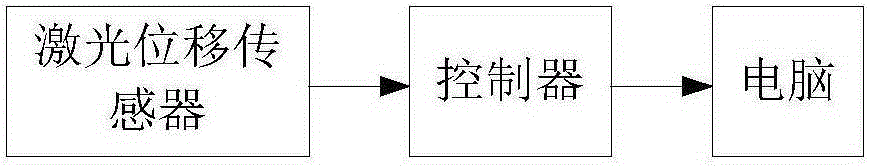
[0032] like image 3 The shown laser displacement sensor 6 is connected with the controller, and the controller and the computer are all connected by cables. The controller provides power ...


PUM


Abstract

The invention discloses an ultrasonic fatigue test vibration displacement monitoring device which is characterized by comprising a calibration table, a laser displacement sensor, a controller and a computer; the laser displacement sensor is connected with the controller and the computer, and the calibration table composes a base, a back plate and a support arm; the base is vertically connected with the back plate, and the support arm is vertically connected with the back plate, is parallel with the base and can move up and down along the back plate to adjust the height; the laser displacement sensor is fixed on the support arm. The ultrasonic fatigue test vibration displacement monitoring device adopts a non-contact manner, the resonance parameter of an ultrasonic fatigue test system is not affect, the test result is not disturbed, and the operation is rapid, simple and convenient.

Description

technical field [0001] The invention discloses a monitoring device, in particular to a vibration displacement measurement and monitoring device for an ultrasonic fatigue test, which is specifically applied to the field of ultrasonic fatigue performance testing of metal materials. Background technique [0002] Ultrasonic fatigue test technology is an accelerated resonance fatigue test method, and its test frequency (20kHz) far exceeds the conventional fatigue test frequency (generally less than 200Hz). Ultrasonic fatigue test research shows that some steel grades up to 10 10 Fatigue fracture will still occur after the secondary stress cycle, and there is no "fatigue limit" shown in the conventional fatigue test curve, so use 10 7 It is not safe to design the fatigue strength based on the fatigue test data of the cycle. The conventional fatigue testing machine frequency of hydraulic servo is lower than 200Hz, it is difficult to provide more than 10 7 The above cycle times, ...

Claims


Application Information

Patent Timeline
Patent Type & Authority Applications(China)
IPC IPC(8): G01N29/30G01B11/02
CPCG01N29/30G01B11/02
Inventor 彭文杰陈一鸣严龙薛欢彭润平邝兰翔
Owner 武汉钢铁有限公司
Why Eureka
Try Eureka