Supercharge Your Innovation With Domain-Expert AI Agents!

Cleaning method of the reaction chamber

A reaction chamber and chamber technology, applied in the field of microelectronics, can solve the problems of inability to completely clean fluorocarbon etching by-products, poor cleaning effect of dry cleaning process, and reduce equipment operation rate, so as to improve equipment operation Efficiency, improved cleaning effect, and improved operating rate

Active Publication Date: 2019-01-18
BEIJING NAURA MICROELECTRONICS EQUIP CO LTD
View PDF3 Cites 0 Cited by
  • Summary
  • Abstract
  • Description
  • Claims
  • Application Information

AI Technical Summary

Problems solved by technology

[0006] First, experiments have shown that even when the optical waveguide technology is used to complete the SiO with a single etching depth of 7 μm 2 After the etching process, the above-mentioned dry cleaning is used to clean the reaction chamber for at least 30 minutes, and the fluorocarbon etching by-products cannot be completely cleaned. The dry cleaning process takes a long time and has a relatively low cleaning effect. Difference
[0007] Second, due to the poor cleaning effect of the above-mentioned dry cleaning process, SiO 2 After the etching process passes through 50RFh, the etching rate will drop rapidly. At this time, the reaction chamber must be opened for wet cleaning and maintenance, resulting in too short a cycle of wet cleaning and maintenance, thereby reducing the operating rate of the equipment

Method used


Image

  • Cleaning method of the reaction chamber
  • Cleaning method of the reaction chamber
  • Cleaning method of the reaction chamber

Examples


Embodiment Construction

[0032] In order to enable those skilled in the art to better understand the technical solution of the present invention, the method for cleaning the reaction chamber provided by the present invention will be described in detail below with reference to the accompanying drawings.

[0033] The cleaning method of the reaction chamber provided by the invention comprises the following steps:

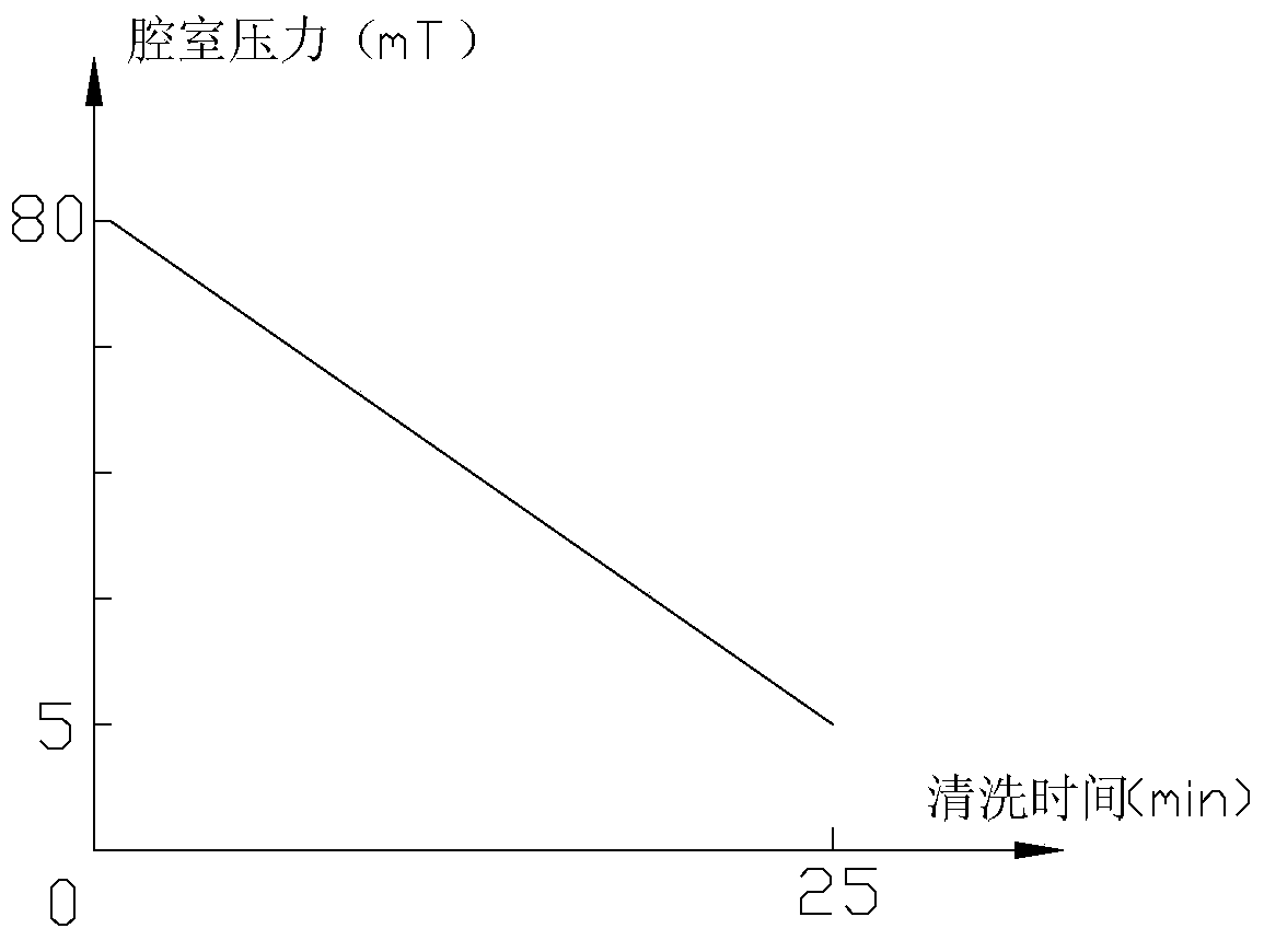
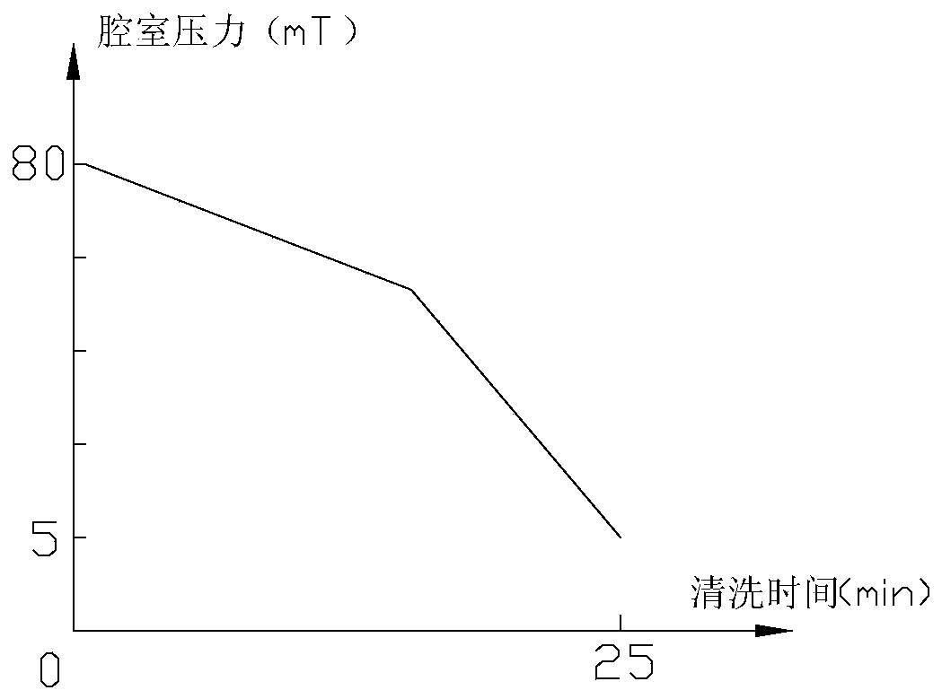
[0034] Perform dry cleaning on the reaction chamber, and adjust the chamber pressure of the reaction chamber according to predetermined rules as the cleaning time increases, so that it decreases from the preset highest pressure value to the lowest pressure value, or automatically The set minimum pressure value rises to the maximum pressure value.

[0035] Among them, the process of dry cleaning is as follows: the cleaning gas is introduced into the reaction chamber, and the power supply of the upper electrode is turned on at the same time, so as to apply the power of the upper electrode to the...


PUM


Abstract

The invention provides a cleaning method for a reaction chamber. The cleaning method comprises the following steps: performing dry-method cleaning on the reaction chamber, adjusting the chamber pressure of the reaction chamber based on rules along with the increase of the cleaning time to enable the pressure to be dropped from a preset highest pressure value to a lowest pressure value, or to enable the pressure to be increased from the preset lowest pressure value to the highest pressure value. The cleaning method for the reaction cavity can shorten the cleaning time as well as can improve the cleaning effect so as to prolong the periods of wet-method cleaning and maintenance.

Description

technical field [0001] The invention relates to the technical field of microelectronics, in particular to a method for cleaning a reaction chamber. Background technique [0002] In recent years, the application of integrated optical waveguide optical devices in the field of communication has gradually increased due to their outstanding advantages of small size, high stability and repeatability, and easy mass production. Among them, for SiO 2 Compared with the traditional shallow etching technology (etching depth below 1 μm), the etching depth of the optical waveguide technology can reach more than 7 μm, and the heavy carbon and heavy fluorine gas is used as the main etching gas (such as C 4 f 8 ) to increase the etch rate. [0003] SiO using optical waveguide technology 2 The typical process configuration is: the chamber pressure is 3-5mT; the power of the upper electrode is 1500W; the power of the lower electrode is 700W; the etching gas includes C 4 f 8 and Ar, wher...

Claims


Application Information

Patent Timeline
Patent Type & Authority Patents(China)
IPC IPC(8): H01L21/67
Inventor 王京谢秋实
Owner BEIJING NAURA MICROELECTRONICS EQUIP CO LTD
Features
  • R&D
  • Intellectual Property
  • Life Sciences
  • Materials
  • Tech Scout
  • Unparalleled Data Quality
  • Higher Quality Content
  • 60% Fewer Hallucinations
Learn More