a coupling structure

A coupled structure and cross-coupling technology, applied in the field of coupled structures, can solve the problems of cumbersome debugging work and complicated design, achieve continuous adjustability and repeatability, improve adjustability, and avoid tedious work.

Active Publication Date: 2019-06-25
SICHUAN JIUZHOU ELECTRIC GROUP
View PDF4 Cites 0 Cited by
  • Summary
  • Abstract
  • Description
  • Claims
  • Application Information

AI Technical Summary

Problems solved by technology

[0004] The embodiment of the present invention provides a coupling structure, which is used to solve the technical problems that the coupling structure of the cross-coupling structure in the prior art has complex design and cumbersome debugging work during use

Method used


Image

  • a coupling structure
  • a coupling structure
  • a coupling structure

Examples


Embodiment

[0037] In the specific implementation process, the coupling structure can be designed in electronic equipment such as terminal equipment, communication equipment, etc., as a module in such electronic equipment, or can be independently designed as a coupling structure. Here, this application does not limit .

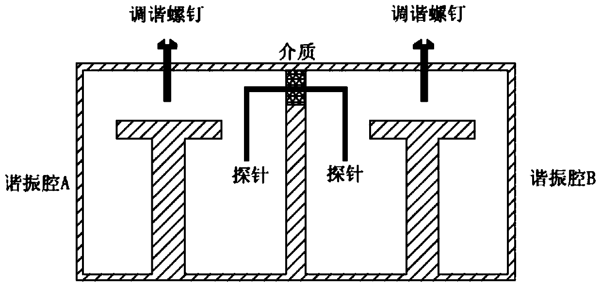
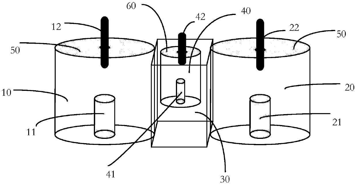
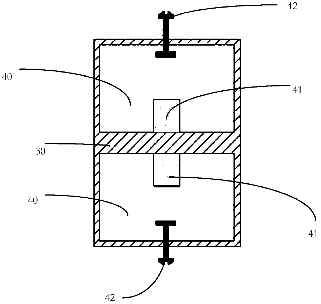
[0038] Please refer to figure 2 , an embodiment of the present invention provides a coupling structure, including:

[0039] The body includes a first surface and a second surface opposite to the first surface, at least a first resonant cavity 10 and a second resonant cavity 20 are dug between the first surface and the second surface, and the first resonant cavity 20 is dug between the first surface and the second surface. The openings of a resonant cavity 10 and the second resonant cavity 20 are all located on the first face, and the first resonant cavity and the second resonant cavity are separated by a partition wall by 30, and the first resonant cavity A first reson...


PUM


Abstract

The invention discloses a coupling structure, which comprises a body and a cross coupler, wherein the body has a first face and a second face opposite to the first face, at least a first resonant cavity and a second resonant cavity are dug between the first face and the second face, openings of the first resonant cavity and the second resonant cavity are both located on the first face, the first resonant cavity and the second resonant cavity are separated via a separation wall, the first resonant cavity is internally provided with a first resonator, and the second resonant cavity is internally provided with a second resonator; the cross coupler at least comprises a cross coupling resonant cavity and is arranged on the separation wall, and the cross coupling resonant cavity is internally provided with a third resonator; and signals inside the first resonant cavity and the second resonant cavity are coupled via the cross coupler. According to the above coupling structure, the technical problems that the cross coupling structure in the prior art is complicated in design, and the debugging work in the case of use is tedious can be solved.

Description

technical field [0001] The invention relates to the field of electronic technology, in particular to a coupling structure. Background technique [0002] Due to the rapid development of electronic information, this makes spectrum resources increasingly scarce. As a frequency selection device, the microwave coupling structure is used to separate or recombine different frequencies. In order to make more effective use of limited spectrum resources and improve communication To improve the anti-interference ability of the system, it is necessary to improve the frequency selection ability of the microwave coupling structure. The ideal frequency selection characteristic is: let the required frequency pass completely, let the unwanted frequency completely suppress. In the actual design, only different functions can be used to approximate the ideal situation. Among them, the "generalized Chebyshev function" is a superior function type, which can greatly improve the frequency selectio...

Claims


Application Information

Patent Timeline
Patent Type & Authority Patents(China)
IPC IPC(8): H01P5/00H01P7/04H01P7/10H01P7/00
CPCH01P5/00H01P7/00H01P7/04H01P7/10
Inventor 任屹灏杨光宋烨曦
Owner SICHUAN JIUZHOU ELECTRIC GROUP
Why Eureka
Try Eureka