Vivaldi antenna and antenna apparatus

An antenna and slot line technology, applied in the structural form of radiating elements, circuits, waveguide horns, etc., can solve the problems of large dielectric loss, electromagnetic wave loss, and complex processing of the director, so as to improve the ability of anti-polarization distortion and gain The effect of increasing the intensity of radiation

Active Publication Date: 2016-02-17
中电科微波通信(上海)股份有限公司
View PDF7 Cites 13 Cited by
  • Summary
  • Abstract
  • Description
  • Claims
  • Application Information

AI Technical Summary

Problems solved by technology

[0005] Adding a medium with a high dielectric constant as a director in the direction of electromagnetic wave radiation is an effective means to increase the gain of the Vivaldi antenna, but the director with a high dielectric c

Method used


Image

  • Vivaldi antenna and antenna apparatus
  • Vivaldi antenna and antenna apparatus
  • Vivaldi antenna and antenna apparatus

Examples


Embodiment 1

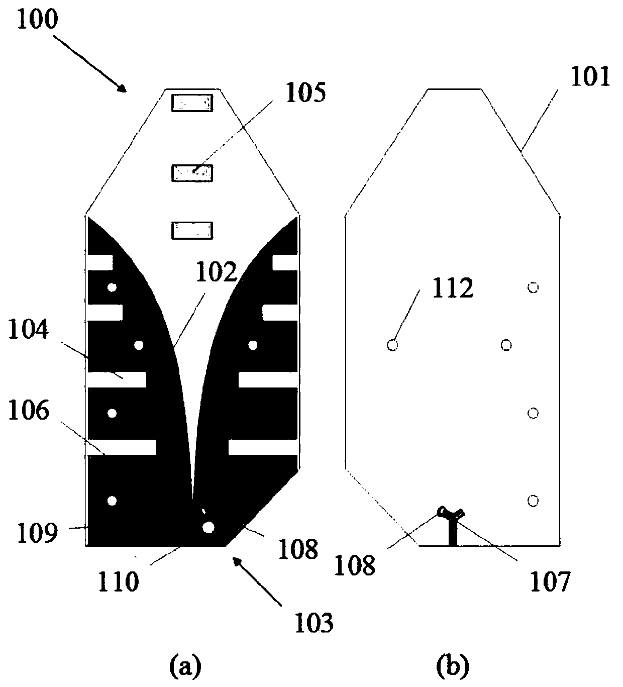
[0028] figure 1 (a) is a schematic diagram of the upper surface of the Vivaldi antenna, figure 1 (b) is a schematic diagram of the structure of the lower surface of the Vivaldi antenna.

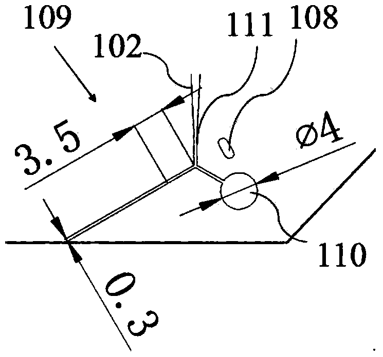
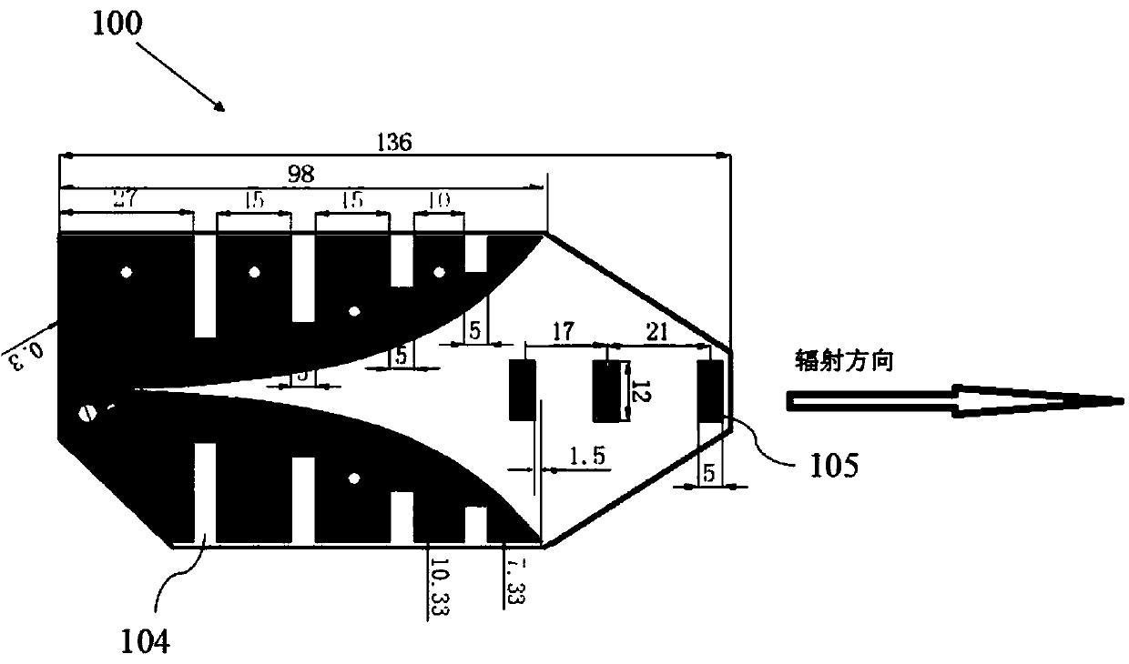
[0029] Such as figure 1 As shown, the Vivaldi antenna 100 includes a dielectric plate 101 , a tapered slot line 102 , a feed unit 103 , eight fences 104 and three directing elements 105 .

[0030] Such as figure 1 As shown in (a), in this embodiment, the size of the dielectric board 101 is 136mm × 63.9mm × 1mm, and the dielectric constant is 4.4. In this embodiment, in order to facilitate installation, the upper and lower corners of the dielectric board 101 are The part is cut into corners, and the size of the corners is only related to the size of the installation unit.

[0031] The upper surface of the dielectric board 101 has a metal layer 106 for conducting current. In this embodiment, the metal layer 106 is a copper sheet pasted on the dielectric board 101 , and the length of the met...

Embodiment 2

[0047] Figure 5 It is a schematic diagram of the external structure of the Vivaldi antenna device.

[0048] Such as Figure 5 As shown, the Vivaldi antenna device 200 includes the Vivaldi antenna 100 described in Embodiment 1 (not shown in the figure) and a radome 201 for protecting the Vivaldi antenna 100 .

[0049] Image 6 It is a partial structural diagram of the Vivaldi antenna device.

[0050] Such as Figure 5 , 6 As shown, the radome 201 includes a base 202, a cover body 203, a ground post 204, a radio frequency connector 205, and L-shaped mounting pieces 206a and 206b.

[0051] The Vivaldi antenna 100 is mounted and fixed on the base 202 through two L-shaped mounting pieces 206a, 206b matched with the five fixing holes 112 and five fixing pieces (not shown in the figure).

[0052] The cover body 203 is installed on the base 202 and covers around the Vivaldi antenna 100 to play a protective role. Such as figure 1 , 6 As shown, in order to facilitate the insta...


PUM


Abstract

The invention provides a Vivaldi antenna. The Vivaldi antenna is characterized by comprising a medium plate of which one face is provided with a metal layer serving as the upper surface of the medium plate, a gradual change groove line arranged on the upper surface of the medium plate, a feed unit arranged on the medium plate, at least two fences arranged at two sides of the gradual change groove line, and at least one guiding oscillator fixed at the opening side of the gradual change groove line, wherein the gradual change groove line is shaped as a horn-shaped opening, the feed unit is used for feeding the gradual change groove line, the at least two fences are used for concentrating an electric current to the groove line, the guiding oscillator is used for guiding an electromagnetic wave to be transmitted to a specified radiation direction, and the length of the guiding oscillator is not larger than one third of the width of the opening of the gradual change groove line.

Description

technical field [0001] The invention relates to the field of wireless communication, in particular to a wide-band miniaturized high-gain Vivaldi antenna and a Vivaldi antenna device. Background technique [0002] Since entering the 21st century, with the rapid development of science and technology, people's lives are increasingly modernized and socialized, and higher requirements have been put forward for the application of electronic technology. Whether it is military communication or civilian communication systems, not only high-quality transmission Language, text, image, data and other information, and requires equipment to be broadband, miniaturized, and high-gain. [0003] As a device for radiating and receiving electromagnetic waves, the antenna is one of the important components in the radio communication system. In the civil communication system, especially the free wireless communication system of rail transit, the channel capacity is continuously expanded and the ...

Claims


Application Information

Patent Timeline
IPC IPC(8): H01Q1/38H01Q13/02
Inventor 莫智超印小忠陈俊华徐凡杨福慧马常彪
Owner 中电科微波通信(上海)股份有限公司
Why Eureka
Try Eureka