
Camera assembling adjusting and calibrating method

A calibration method and camera technology, applied in image communication, TV, color TV parts, etc., can solve the problems of inconsistent performance indicators of different cameras, low aiming and positioning accuracy, etc., reduce after-sales maintenance and rework costs, and have strong practicability , The effect of improving interchangeability

Inactive Publication Date: 2016-02-17
LUOYANG INST OF ELECTRO OPTICAL EQUIP OF AVIC
View PDF7 Cites 21 Cited by
  • Summary
  • Abstract
  • Description
  • Claims
  • Application Information

AI Technical Summary

Problems solved by technology

[0003] The purpose of the present invention is to provide a camera assembly and calibration method to solve the inconsistencies in the performance indicators of different cameras caused by errors such as inclination and offset of the CCD imaging surface relative to the optical axis after the camera is assembled and debugged. The problem of low precision

Method used


Image

  • Camera assembling adjusting and calibrating method
  • Camera assembling adjusting and calibrating method
  • Camera assembling adjusting and calibrating method

Examples


Embodiment 1

[0021] Camera adjustment and calibration method, including the following steps:

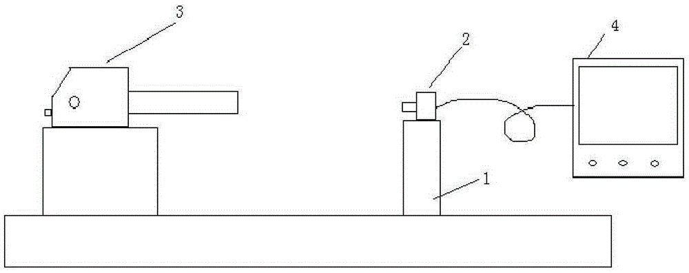
[0022] 1) if figure 1 As shown, the bracket 1 for fixing the camera 2 is correspondingly provided with positioning pins matched with the installation base of the camera 2, and the camera 2 which has been preliminarily assembled (the lens part has been assembled and is fixed on the front of the camera) is fixed by using the positioning pins. on bracket 1;

[0023] Place an autocollimator 3 directly opposite the camera 2, roughly align the camera 2, turn on the autocollimator 3 and send out the calibration laser, since the outermost lens of the camera 2 is a filter, directly fine-tune the autocollimation The instrument 3 (such as pitch angle, left and right offset angle, etc.) makes the adjustment laser return along the original optical path through the filter, that is, the optical axis of the autocollimator 3 is perpendicular to the front filter of the lens of the camera 2, that is, The optical ...

Embodiment 2

[0030] Camera adjustment and calibration method, the operation is basically the same as embodiment 1. Since the outermost part of the camera lens is not a filter, in step 1), it is necessary to install a high-precision flat reflector on the front reference surface of the camera lens, and then fine-tune the autocollimator (such as pitch angle, left and right offset angle, etc.), Make the adjustment laser return along the original optical path through the plane reflector.


PUM


Abstract

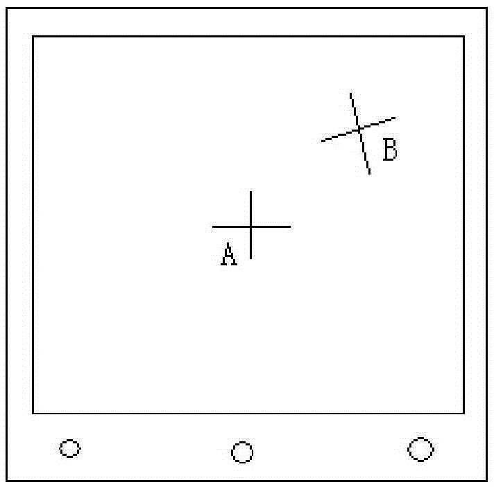
The invention discloses a camera assembling adjusting and calibrating method and belongs to the technical field of bare camera assembling. The method comprises the following steps that firstly, an autocollimator and a camera are arranged in a direct facing mode, the position of the camera is fixed, and the autocollimator is adjusted to make the light axis of the autocollimator to be parallel to the light axis of a lens of the camera; secondly, the camera images a cross target source of the autocollimator, the central cross line of an image and the cross line of the target source are displayed on a displayer, a CCD imaging circuit board is adjusted in an installation plane, and the central cross line of the image is made to coincide with the cross line of the target source; thirdly, the camera is taken down, another camera to be debugged is fixed to the same position, and the same operation in the second step is carried out. The camera assembling adjusting and calibrating method is simple and high in practicability, and the problems that in the prior art, after assembling debugging of cameras, different cameras are not consistent in performance index and low in aiming positioning precision due to errors that the CCD imaging surface is inclined or deflected relative the light axis can be effectively solved.

Description

technical field [0001] The invention relates to a camera assembly and calibration method, belonging to the technical field of optical-mechanical assembly. Background technique [0002] The camera is composed of lens and CCD imaging and processing circuit. After the lens is assembled and debugged, it is fixed on the front of the camera by positioning the mounting surface. However, during the assembly and debugging process, there is no adjustment link for the CCD imaging surface, and the position of the CCD is guaranteed by the processing accuracy of the circuit board. Therefore, after installation, there will be errors such as the tilt, rotation, and offset of the CCD imaging surface relative to the optical axis, which will lead to the camera installed at the same position. The technical indicators are inconsistent, and the positioning accuracy of the system to the direction is unstable. In addition, the field of view of some cameras deviates greatly and needs to be re-adju...

Claims


Application Information

Patent Timeline
IPC IPC(8): H04N5/225
CPCH04N23/54
Inventor 孔小辉
Owner LUOYANG INST OF ELECTRO OPTICAL EQUIP OF AVIC
Learn More