
Image sensor, sunspot removal method and sunspot removal device thereof

An image sensor and sunspot technology, which is applied in the field of image processing, can solve the problems of too much noise in the sampling circuit, easy misjudgment of the digital method, inaccurate judgment of the sunspot phenomenon, etc., and achieve the effect of reducing noise

Active Publication Date: 2018-09-11
BYD SEMICON CO LTD
View PDF5 Cites 0 Cited by
  • Summary
  • Abstract
  • Description
  • Claims
  • Application Information

AI Technical Summary

Problems solved by technology

[0004] Carrying out sunspot removal by digital mode and analog mode in the related art has the following disadvantages: 1, the digital mode is easy to misjudgment, namely inaccurate judgment of whether sunspot phenomenon occurs
2. In the analog way, the fixed level generated by the fixed level generating circuit is used as the reset sampling level to correct the sunspot. Although there will be no misjudgment, it will bring too much noise to the sampling circuit.

Method used

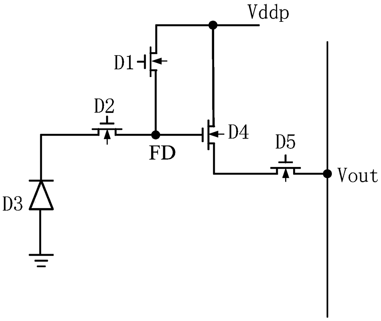
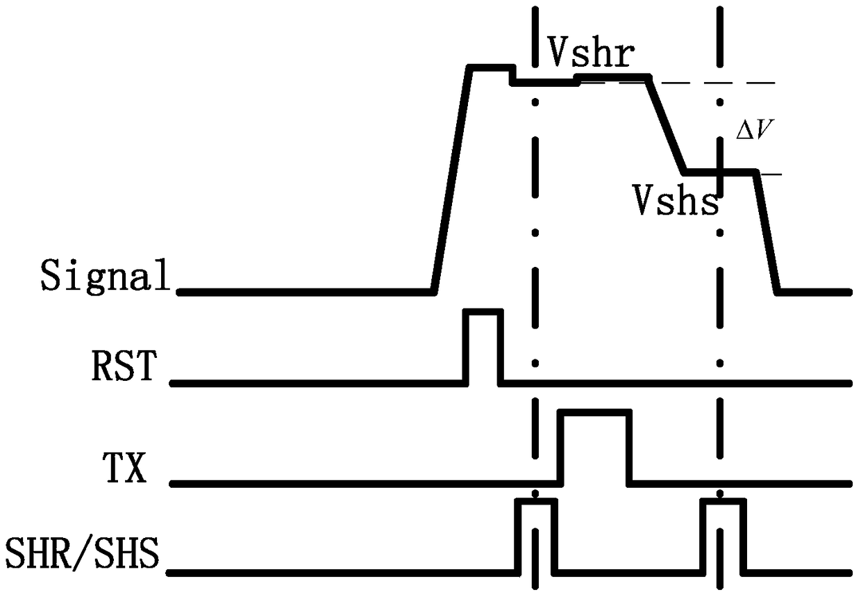
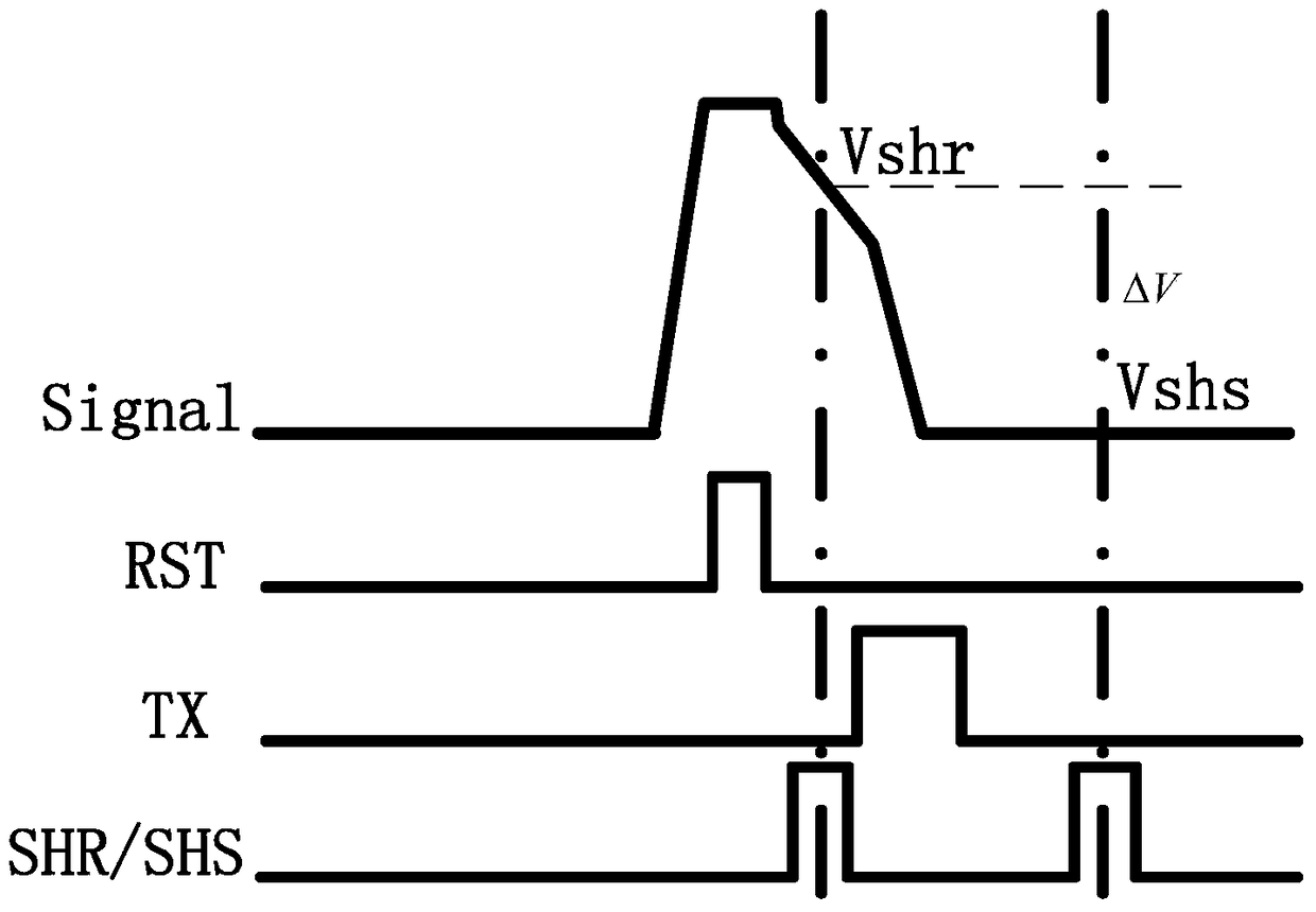

Image

  • Image sensor, sunspot removal method and sunspot removal device thereof
  • Image sensor, sunspot removal method and sunspot removal device thereof
  • Image sensor, sunspot removal method and sunspot removal device thereof

Examples


Embodiment Construction

[0026] The embodiments of the present invention are described in detail below. Examples of the embodiments are shown in the accompanying drawings, in which the same or similar reference numerals indicate the same or similar elements or elements with the same or similar functions. The embodiments described below with reference to the accompanying drawings are exemplary, and are only used to explain the present invention, and cannot be construed as limiting the present invention.

[0027] The following disclosure provides many different embodiments or examples for implementing different structures of the present invention. In order to simplify the disclosure of the present invention, the components and settings of specific examples are described below. Of course, they are only examples, and are not intended to limit the invention. In addition, the present invention may repeat reference numbers and / or letters in different examples. This repetition is for the purpose of simplificat...


PUM


Abstract

The invention discloses a method for removing sunspots of an image sensor, comprising: obtaining a reset sampling signal value of a pixel unit in an image sensor pixel array; Generate a comparison signal when the value is less than the preset sampling signal threshold; generate the position information corresponding to the pixel unit of the reset sampling signal value according to the comparison signal; replace the reset sampling signal value corresponding to the position information with the brightest value of the image to remove the pixel unit corresponding to the position information sun spots. The sunspot removal method of the image sensor of the present invention can accurately remove all sunspots without using a fixed level value as the reset sampling signal value, effectively reducing the noise of the signal chain. The invention also discloses a device for removing sunspots of an image sensor and an image sensor comprising the device for removing sunspots of the image sensor.

Description

Technical field [0001] The present invention relates to the technical field of image processing, and in particular to a method for removing sun spots of an image sensor, a device for removing sun spots of an image sensor, and an image sensor of a device for removing sun spots including the image sensor. Background technique [0002] Complementary metal oxide semiconductor field effect image sensors are referred to as CMOS (Complementary Metal Oxide Semiconductor, complementary metal oxide semiconductor) image sensors. The main components of CMOS image sensors are analog signal processing parts and digital image signal processing parts. Specifically, the CMOS image sensor mainly includes a PixelArray (pixel unit), a control circuit, an analog front-end processing circuit, an A / D converter, an image signal processing circuit, and related storage units. With the development of CMOS image sensors, people's research on CMOS image sensors has become more and more in-depth, and its perf...

Claims


Application Information

Patent Timeline
Patent Type & Authority Patents(China)
IPC IPC(8): H04N5/374H04N5/359
CPCH04N23/71H04N25/50H04N25/76
Inventor 刘坤郭先清傅璟军
Owner BYD SEMICON CO LTD
Learn More