Adjustable vibration type bar screening equipment

A bar screen and sub-equipment technology, which is applied in the direction of filter screen, solid separation, grid, etc., can solve the problems of high excitation force and power, increased blanking potential energy, and reduced service life of bar screen, etc., to achieve exciting The vibration force and power are reduced, the effect of reducing the impact of potential energy and prolonging the service life

Active Publication Date: 2016-02-24
天津百利阳光环保设备有限公司
View PDF6 Cites 9 Cited by
  • Summary
  • Abstract
  • Description
  • Claims
  • Application Information

AI Technical Summary

Problems solved by technology

[0002] In the field of material classification and processing, the existing vibrating bar screening equipment has a single-layer bar sieve structure, and the whole machine vibrates with the material during operation. In this way, the exciting force and power of the vibrating motor are required to be large. , and in order to speed up the discharge of large material on the bar screen, it is necessary to increase the angle of the bar and the vibration frequency of the motor. The increase in the angle of the bar will lead to an increase in the blanking potential energy, which will cause more damage to the bar screen. The large impact will reduce the service life of the bar screen. In addition, the inclination angle of the bar screen cannot be adjusted. In this way, the applicability to materials with different properties is poor.

Method used


Image

  • Adjustable vibration type bar screening equipment
  • Adjustable vibration type bar screening equipment

Examples


Embodiment Construction

[0020] In order to further understand the invention content, characteristics and effects of the present invention, the following examples are given, and detailed descriptions are as follows in conjunction with the accompanying drawings:

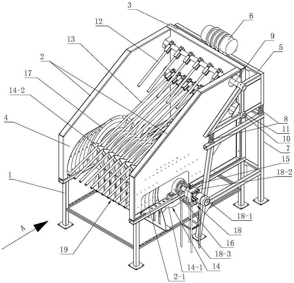
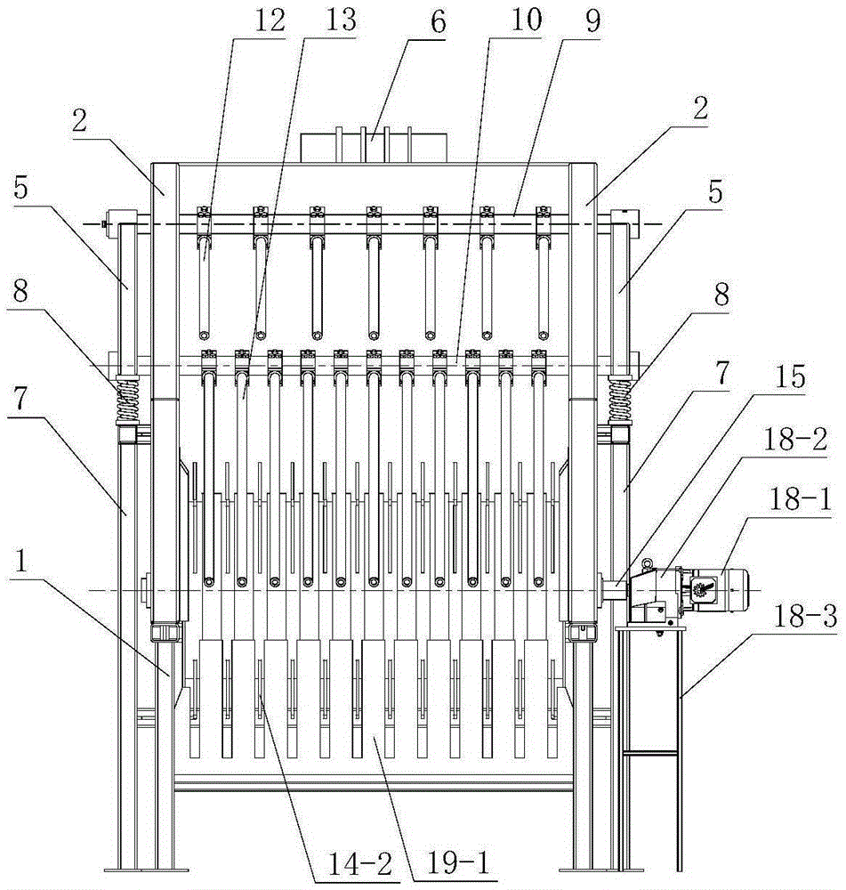
[0021] see Figure 1-2 , an adjustable vibrating rod screening equipment, consists of the following parts:

[0022] Including a frame 1, the frame is a frame structure welded by section bars. The upper end of the frame is provided with two side plates 2 and a tailgate 3, and the front ends of the two side plates are open ends, forming a large material discharge end 4.

[0023] Comprise vibrating stand 5, and vibrating stand surrounds and is located at outside two side plates and tailgate. At least one vibrating motor 6 is installed on the vibrating frame, and a vibrating supporting frame 7 is arranged below the vibrating frame, and the vibrating frame is floated and supported on the vibrating supporting frame by a plurality of damping sprin...


PUM


Abstract

The invention discloses adjustable vibration type bar screening equipment. The adjustable vibration type bar screening equipment comprises a frame, wherein two side plate and a back baffle plate are arranged at the upper end of the frame; the front ends of the two side plates are large material discharge ends; a vibration frame is arranged at the outer peripheries of the two side plates and the back baffle plate, and is supported on a vibration support frame in a floating manner through multiple vibration reducing springs; a vibration motor and first and second shafts, vertically arranged, are mounted on the vibration frame; multiple short bars are mounted on the first shaft to form an upper-layer bar screen; multiple long bars are mounted on the second shaft to form a lower-layer bar screen; poking drums consisting of drum bodies and multiple sets of poking teeth are arranged in the positions of the large material discharge ends, and are fixedly supported on the frame in a front-back adjusting manner; the two ends thereof are respectively provided with baffle plates; a driving mechanism is arranged outside the side plate at one side; and the lower ends of the multiple long bars are freely arranged on the drum bodies, and are inserted between the axially arranged poking teeth one by one. The equipment prolongs the service life of the bar screens, reduces the exciting force, the vibration frequency and the power of the vibration motor, and improves the large material discharge speed of the bar screens.

Description

technical field [0001] The invention relates to classification treatment equipment for blocky and medium and small particle materials, in particular to an adjustable vibrating bar screening equipment. Background technique [0002] In the field of material classification and processing, the existing vibrating bar screening equipment has a single-layer bar sieve structure, and the whole machine vibrates with the material during operation. In this way, the exciting force and power of the vibrating motor are required to be large. , and in order to speed up the discharge of the large material on the bar screen, it is necessary to increase the angle of the bar and the vibration frequency of the motor. The increase in the angle of the bar will lead to an increase in the potential energy of the blanking, which will cause more damage to the bar screen. Large impact will reduce the service life of the bar screen. In addition, the inclination angle of the bar screen cannot be adjusted,...

Claims


Application Information

Patent Timeline
Patent Type & Authority Applications(China)
IPC IPC(8): B07B1/14B07B1/42B07B1/46
CPCB07B1/14B07B1/42B07B1/46
Inventor 何佩珍傅磊孙涛孙希财孙国瑞
Owner 天津百利阳光环保设备有限公司
Why Eureka
Try Eureka