
Integrated heater of core-making fluid

A heater, integrated technology, used in manufacturing tools, metal processing equipment, parts of molding machines, etc., can solve the problems of leakage, inability to achieve high heat exchange efficiency, bulky and other problems, and achieve easy installation, miniaturization, and heat exchange. The effect of increasing the area

Inactive Publication Date: 2016-02-24
SUZHOU MINGZHI TECH
View PDF9 Cites 2 Cited by
  • Summary
  • Abstract
  • Description
  • Claims
  • Application Information

AI Technical Summary

Problems solved by technology

In the prior art, there are usually two ways of directly heating the fluid by electric heating or indirectly heating the fluid by heating the heat transfer medium. The pipeline heater is such a structure. This type of structure usually adopts a welded and assembled structure. Affected by many factors such as processing and assembly, the design of the flow channel is relatively regular, and it is impossible to achieve high heat exchange efficiency per unit volume, and there is also a relatively high risk of leakage, and the volume is relatively large

Method used


Image

  • Integrated heater of core-making fluid
  • Integrated heater of core-making fluid
  • Integrated heater of core-making fluid

Examples


Embodiment 1

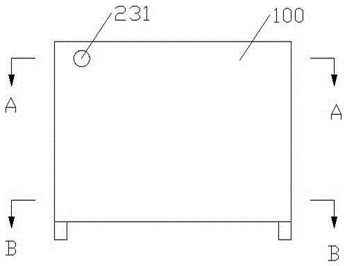
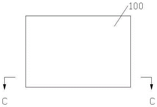
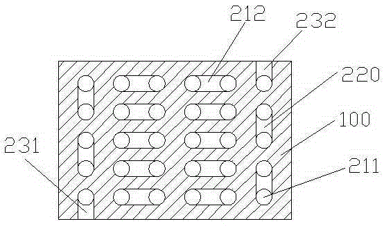
[0025] Embodiment one: see Figure 1 to Figure 5 , as shown in the legend therein, an integral heater for core-making fluid, used for heating air, includes an integrally cast heating body 100, the heating body 100 is provided with a flow channel structure, the flow channel structure includes along X Five flow channel units arranged in sequence along the axis direction and four transition flow channels 220 extending along the X-axis direction, each flow channel unit includes six main body flow channels 211 arranged in sequence along the Y-axis direction and extending along the Z-axis direction, and four transition flow channels 220 extending along the Y-axis direction. Five detour channels 212 extending in the axial direction, the detour channels 212 communicate with the ports of two adjacent body channels 211 , and the transition channels 220 communicate with the body channels 211 of adjacent channel units.

[0026] The two free ports of the body flow channel of the above-ment...

Embodiment 2

[0033] The rest is the same as the first embodiment, except that the integral heater is heated by gas, the heating body is reserved with a gas heating cavity, and the flow channel structure is arranged around the gas heating cavity.

Embodiment 3

[0035] The rest is the same as in Embodiment 1, except that the five flow channel units are arranged in sequence along the first setting direction, the above-mentioned transition flow channels extend along the first setting direction, and the above-mentioned six body flow channels are sequentially arranged along the second setting direction Arranged, the above-mentioned body flow channel extends along the third setting direction, the above-mentioned roundabout flow channel is arranged in sequence along the second setting direction, the above-mentioned first setting direction, the above-mentioned second setting direction and the above-mentioned third setting direction are not on the same plane Inside, the first set direction and the second set direction form an angle A, the first set direction and the third set direction form an angle B, the second set direction and the third set direction The set direction forms an included angle C, the angle range of the above-mentioned angle ...


PUM


Abstract

The invention discloses an integrated heater of core-making fluid. The integrated heater comprises an integrally poured and molded heating body, wherein the heating body is provided with a runner structure; the runner structure comprises runner units successively arranged along a first set direction and transition runners extended along the first set direction; each runner unit comprises body runners successively arranged along a second set direction and extended along a third set direction and circuitous runners extended along the second set direction; the circuitous runners are used for connecting ports of two adjacent body runners; the transition runners are used for connecting the body runners of the adjacent runner units; the runner structure extends along a substantially-S-shaped direction of the first set direction and the second set direction, so that the heat exchange area between the fluid of the heating body and the heating body is increased; the fluid heating speed is significantly improved; meanwhile, the heating body and the runner structure are integrated to be a whole structure; the sealing performance of the runner is ensured; the integrated heater can heat various fluids; the pollution to the environment caused by leakage is avoided.

Description

technical field [0001] The invention relates to the field of fluid heating, in particular to a fluid heater suitable for fluid heating occasions such as core box air blowing and core box heating of a foundry equipment core making machine. Background technique [0002] In many different applications, it is necessary to rapidly increase the temperature of the fluid to achieve a higher service temperature, for example, to provide ready-to-use high-temperature liquids or gases for homes, offices, campuses, and industrial processes. In the prior art, there are usually two ways of directly heating the fluid by electric heating or indirectly heating the fluid by heating the heat transfer medium. The pipeline heater is such a structure. This type of structure usually adopts a welded or assembled structure. Affected by many factors such as processing and assembly, the design of the flow channel is relatively regular, and it is impossible to achieve high heat exchange efficiency per u...

Claims


Application Information

Patent Timeline
Patent Type & Authority Applications(China)
IPC IPC(8): B22C19/00B22C7/06
CPCB22C19/00B22C7/06
Inventor 徐磊磊
Owner SUZHOU MINGZHI TECH
Learn More