
A Variable Stiffness Joint Based on Torsion Spring Characteristics

A technology of variable stiffness and torsion spring, applied in the field of variable stiffness joints based on the characteristics of torsion springs, it can solve the problems of many parts, difficult to guarantee variable stiffness performance, and small variable stiffness range, so as to achieve good constant stiffness performance and adjust stiffness loss. low effect

Active Publication Date: 2017-04-12
HARBIN INST OF TECH
View PDF5 Cites 0 Cited by
  • Summary
  • Abstract
  • Description
  • Claims
  • Application Information

AI Technical Summary

Problems solved by technology

[0003] The content of the present invention is to solve the defects of stiffness joints in the prior art that energy saving is not enough, variable stiffness performance is difficult to guarantee, the range of variable stiffness is small, and the sliding friction loss of the fulcrum in the groove is adjusted by moving the fulcrum position based on the principle of leverage. It can solve the problems of large capacity, need many parts and unreasonable structural design, and then provide a variable stiffness joint based on torsion spring characteristics

Method used


Image

  • A Variable Stiffness Joint Based on Torsion Spring Characteristics
  • A Variable Stiffness Joint Based on Torsion Spring Characteristics
  • A Variable Stiffness Joint Based on Torsion Spring Characteristics

Examples


specific Embodiment approach 1

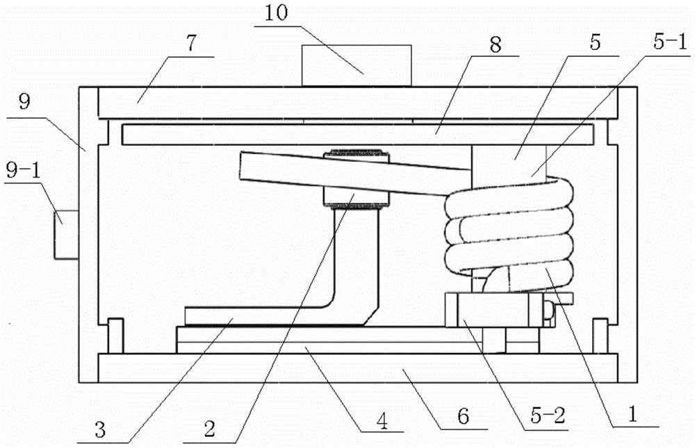
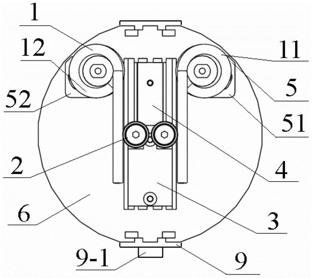
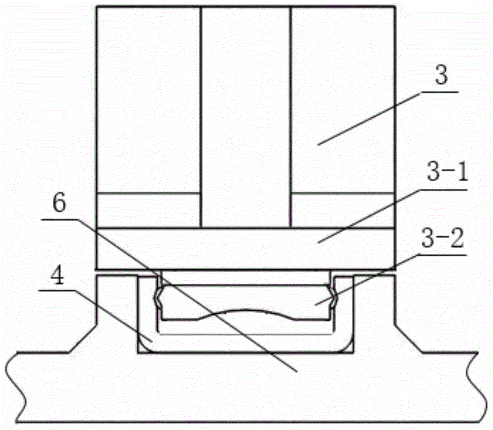
[0012] Specific implementation mode one: combine Figure 1-Figure 5 This embodiment is described. A variable stiffness joint based on torsion spring characteristics in this embodiment includes a set of torsion springs 1, sliders 3, slide rails 4, a first output disc 6, a second output disc 7, an input Disk 8, input disk shaft 10, two rollers 2, a set of torsion spring brackets 5 and two connectors 9, a set of torsion springs 1 includes a first torsion spring 11 and a second torsion spring 12, a set of torsion spring brackets 5 includes a first torsion spring bracket 51 and a second torsion spring bracket 52; the first output disk 6, the second output disk 7 and the input disk 8 are all discs, and the first output disk 6 and the second output disk 7 are arranged oppositely, The first output disk 6 and the second output disk 7 are fixedly connected by two connectors 9, and the two connectors 9 are arranged symmetrically, the input disk rotating shaft 10 is inserted on the second...

specific Embodiment approach 2

[0013] Specific implementation mode two: combination figure 1 and figure 2 Describe this embodiment, the variable stiffness joint based on torsion spring characteristics in this embodiment, the first torsion spring 11 and the second torsion spring 12 have the same structure, and the first torsion spring 11 and the second torsion spring 12 The direction of rotation is opposite, the first torsion spring 11 and the second torsion spring 12 are axisymmetrically arranged on both sides of the slide rail 4, and the first torsion spring bracket 51 and the second torsion spring bracket 52 are symmetrically arranged on both sides of the slide rail 4 , the others are the same as in the first embodiment.

specific Embodiment approach 3

[0014] Specific implementation mode three: combination figure 1 and figure 2 This embodiment is described. In this embodiment, a variable stiffness joint based on torsion spring characteristics is described. One of the two connectors 9 is processed with an output rod installation interface end 9-1. Others and specific implementation Method 1 is the same.


PUM


Abstract

The invention relates to a variable-rigidity joint, in particular to a variable-rigidity joint based on characteristics of torsional springs. The variable-rigidity joint aims at solving the defects that in the prior art, energy saved by an existing rigid joint is not enough, variable-rigidity performance cannot be ensured easily and the variable-rigidity range is small, and aims at solving the problems that in the rigidity regulation manner that the position of a fulcrum is moved based on the lever principle, energy consumption generated when the fulcrum conducts sliding friction in a groove is large, the number of required parts is large and the structural design is not reasonable. The variable-rigidity joint comprises the set of torsional springs, a slide block, a slide rail, a first output plate, a second output plate, an input plate, an input plate rotating shaft, two rollers, a set of torsional spring supports and two connection pieces. The set of torsional springs include the first torsional spring and the second torsional spring. The set of torsional spring supports include the first torsional spring support and the second torsional spring support. The first output plate, the second output plate and the input plate are all disks. The variable-rigidity joint is used for the field of robot joints.

Description

technical field [0001] The invention relates to a variable stiffness joint, in particular to a variable stiffness joint based on torsion spring characteristics. Background technique [0002] The variable stiffness joint is a kind of flexible joint with adjustable stiffness which is different from the traditional rigid joint. Due to the controllability of its own stiffness, it can adapt to the needs of more different application environments. With the development of the robot industry and applications, human beings come into contact with robots more and more frequently in production and life. The safety issue of human-machine collaboration is attracting people's attention. However, since the 1970s, there have been many incidents of robots hurting people around the world. The occurrence of these deplorable incidents reminds people of the importance of human-machine collaboration safety and the urgency of research in related fields. In addition, due to the adjustable stiffn...

Claims


Application Information

Patent Timeline
Patent Type & Authority Patents(China)
IPC IPC(8): B25J17/00
CPCB25J17/00
Inventor 杨德财金弘哲刘章兴赵杰朱延河
Owner HARBIN INST OF TECH
Learn More