Integrated wall surface system
An integrated, wall-beam technology, applied to walls, building components, buildings, etc., can solve the problems of unsightly exposed screws, large errors, and easy water seepage, and achieve the effects of reduced labor costs, convenient construction, and high connection fastness
- Summary
- Abstract
- Description
- Claims
- Application Information
AI Technical Summary
Problems solved by technology
Method used
Image
Examples
Embodiment 1
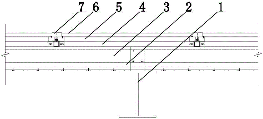
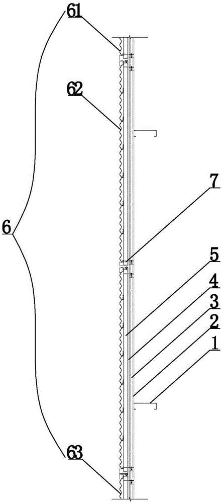
[0028] The integrated wall system of this embodiment combines figure 1 , figure 2 , including steel columns 1, inner panels 2, thermal insulation cotton 3, wall beams, wall panels 6 and accessories 7, the wall beams include C-shaped wall beams 4 and secondary wall beams 5, and wall panels 6 are installed on secondary wall beams 5 through accessories 7 On the outside, the secondary wall beam 5, C-shaped wall beam 4, thermal insulation cotton 3, and inner panel 2 are installed in sequence from outside to inside, and the inner panel 2 is fixed by steel column 1, which is an H-shaped steel column, and wall panel 6 includes the top panel 61. The bottom plate 62 and several intermediate plates 63 installed between the top plate 61 and the bottom plate 62, the top plate 61 is composed of the fixed end 1 611 and the fastening end 1 612, and the bottom plate 63 is composed of the fastening end 2 632 and the fixed end 2 631 , the middle plate 62 is composed of a head end 621, a body 6...
Embodiment 2
[0036] The setting and working principle of the integrated wall system of this embodiment are the same as that of Embodiment 1, the difference is that the wall panel 6 includes a top plate 61, a bottom plate 62 and several intermediate plates 63 installed between the top plate 61 and the bottom plate 62, the top plate 61 It is composed of a fixed end 611 and a fastening end 1 612. The bottom plate 63 is composed of a fastening end 2 632 and a fixed end 631. The middle plate 62 is composed of a head end 621, a body 622 and a tail end 623. The body 622 is wavy and relatively Between the adjacent middle boards, the rear end of the previous middle board is mated with the head end of the rear middle board, and is mated with the fastening end 612 of the top board 61 at the top, and is connected with the fastening end 612 of the bottom board 63 at the bottom. Two 632 mating connections.
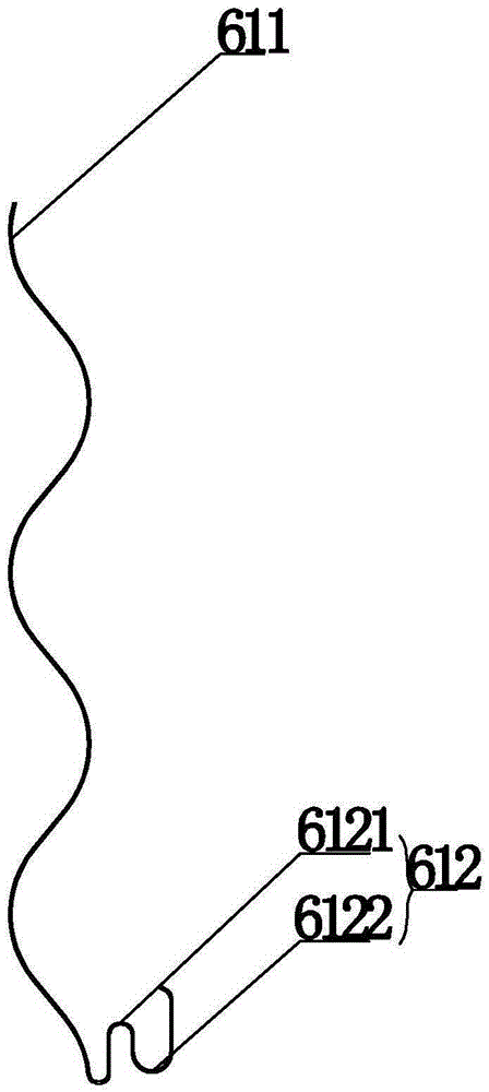
[0037] Specifically in this embodiment, combined with image 3 , in the top plate 61, the faste...
Embodiment 3
[0045] The setting and working principle of this embodiment are the same as that of Embodiment 2, the difference is that the first slot 6121 and the first matching slot 6122 are split structures, wherein the first slot 6121 is movably installed on the lower end of the top plate 61, and the first matching slot 6122 Then it is movably installed at the end of the card slot one 6121; the card tooth one 6211, the fastening groove one 6212 and the fastening section one 6213 are of a split structure, and the card slot two 6231 and the matching groove two 6232 are of a split structure, wherein the card teeth One 6211, fastening groove one 6212, fastening section 6213, card groove two 6231, and matching groove two 6232 are movably installed on the upper and lower ends of the body 622; latch two 6321, fastening groove two 6322 and fastening section two 6323 are Split structure, the second locking tooth 6321 , the second fastening groove 6322 and the second fastening section 6323 are mova...
PUM
 Abstract
Description
Claims
Application Information
 - R&D
- Intellectual Property
- Life Sciences
- Materials
- Tech Scout
- Unparalleled Data Quality
- Higher Quality Content
- 60% Fewer Hallucinations
Browse by: Latest US Patents, China's latest patents, Technical Efficacy Thesaurus, Application Domain, Technology Topic, Popular Technical Reports.
© 2025 PatSnap. All rights reserved.Legal|Privacy policy|Modern Slavery Act Transparency Statement|Sitemap|About US| Contact US: help@patsnap.com


