Pressurization no-leakage piezoelectric control type gas injection device

A technology of supercharging control and injection device, which is applied in the direction of fuel injection device, charging system, engine components, etc., can solve the problem of unfavorable valve core precise control, affecting engine power and fuel economy, and reducing gas injection pressure and injection rate. and other problems, to achieve the effect of improving power performance and fuel economy, meeting the requirements of system injection stability and high control accuracy

Active Publication Date: 2016-02-24
HARBIN ENG UNIV
View PDF7 Cites 7 Cited by
  • Summary
  • Abstract
  • Description
  • Claims
  • Application Information

AI Technical Summary

Problems solved by technology

[0003] The existing in-cylinder direct-injection dual-fuel engines mostly use an electromagnetically controlled gas injection device, and use a high-pressure pump to compress the gas to a specified pressure. The disadvantages are: the high-pressure pump has a complex structure and there are matching problems, and the boosted gas is transferred from the high-pressure pump The path to the gas injection device through the common rail pipe is long, and the pressure fluctuation is large; the gas injection device uses pressure gas to lift the valve core, but due to the strong compressibility of the gas, it is not conducive to the precise control of the valve core movement, and the gas injection is unstable; In addition, during the gas injection process, with the movement of the valve core, the leakage of gas to the solenoid valve end through the gap between the valve core and the valve body intensifies, resulting in a decrease in the gas injection pressure and injection rate, which has a negative impact on the stability of the gas injection , affecting engine power and fuel economy

Method used


Image

  • Pressurization no-leakage piezoelectric control type gas injection device
  • Pressurization no-leakage piezoelectric control type gas injection device
  • Pressurization no-leakage piezoelectric control type gas injection device

Examples


Embodiment Construction

[0019] The present invention is described in more detail below in conjunction with accompanying drawing example:

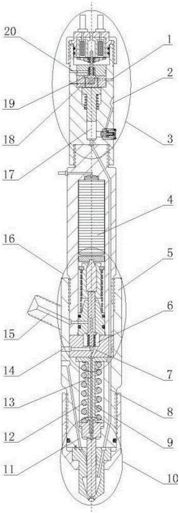
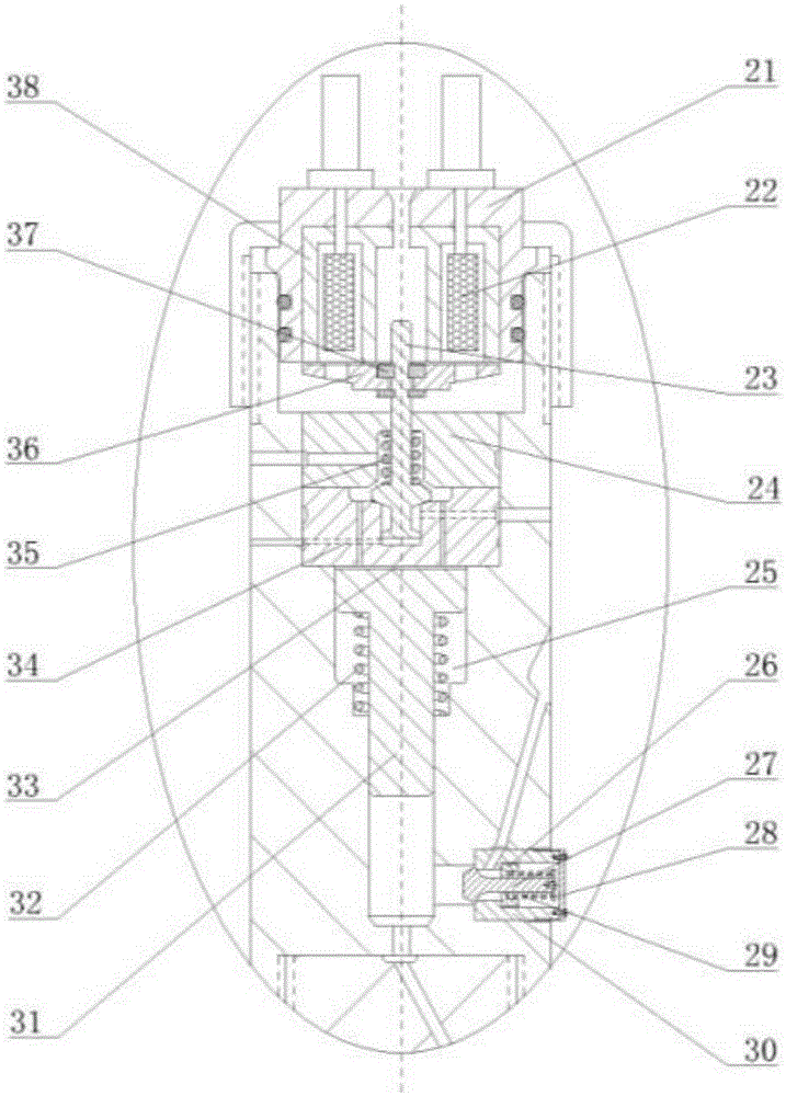
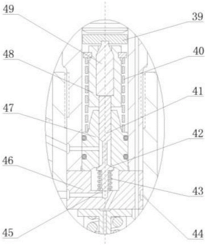
[0020] combine Figure 1~4, the pressurized non-leakage piezoelectric control type gas injection device of the present invention mainly includes a gas booster part 3, a piezoelectric control part 16, a gas nozzle part 10, a piezoelectric element 4, an injection device casing 5, and a needle valve limit rod 9 , Needle valve reset spring 12, pressurized oil inlet oil passage 1, pressurized oil discharge oil passage 20, air inlet 2, air intake passage 8, control oil inlet oil passage 15, control oil return oil passage 14 , Center oil passage 13, sealing oil inlet oil passage 11. The gas booster part 3 is composed of a booster piston 31, a booster piston upper cavity 33, a booster piston lower cavity 17, a booster piston return spring 32, a booster piston return spring chamber 25, an electromagnet 38, an electromagnetic valve body 21, a coil 22. Armature 36, stop ri...


PUM


Abstract

The invention aims to provide a pressurization no-leakage piezoelectric control type gas injection device; and the device comprises a gas pressurization part, a piezoelectric control part, a gas nozzle part, a piezoelectric element, an injection device shell, a needle valve limiting rod, a needle valve return spring, a pressurization oil inlet way, a pressurization oil drainage way, an air inlet, an air intake channel, a control oil inlet way, a control oil return way, a center oil way, a sealing oil inlet way and the like. The pressurization oil inlet way enters the gas pressurization part; the control oil inlet way enters the gas nozzle part through the piezoelectric control part and the needle valve limiting rod; the sealing oil inlet way enters the gas nozzle part through the injection device shell; and the air intake channel enters the gas nozzle part through the gas pressurization part, the piezoelectric control part and the injection device shell. The pressurization no-leakage piezoelectric control type gas injection device is high in gas injection stability and consistency, can satisfy the system injection rule variability requirement, and can preferably solve the problem of gas leakage through a needle valve matching part.

Description

technical field [0001] The invention relates to an engine, specifically a gas injection device for a dual-fuel engine. Background technique [0002] At present, gaseous fuel (such as natural gas), which is one of clean new energy sources, has attracted people's attention due to its advantages of abundant reserves, low price and low pollution emissions. Therefore, the use of gaseous fuel as an alternative fuel for engines has a good development prospect. Engines burning gaseous fuel mainly include spark ignition single-fuel gas engines and diesel ignition dual-fuel engines. Although the spark-ignition single-fuel gas engine has clean emissions, the gas fuel used has low energy density, high fuel consumption, and limited use direction; while the diesel-ignition dual-fuel engine can flexibly switch between the two fuels when used, fuel substitution High efficiency, good power, economy and emission. [0003] The existing in-cylinder direct-injection dual-fuel engines mostly us...

Claims


Application Information

Patent Timeline
IPC IPC(8): F02M51/06
CPCF02M51/0603
Inventor 范立云彭怀利马修真李文辉董晓露孙军
Owner HARBIN ENG UNIV
Why Eureka
Try Eureka