Efficient refrigerator oil separation device

A technology of refrigeration oil and separation device, applied in refrigerators, refrigeration components, refrigeration and liquefaction, etc., can solve problems such as the inability to achieve rapid and efficient separation of refrigeration oil, and achieve the goal of accelerating refrigerant gasification, increasing separation speed, and increasing temperature. Effect

Inactive Publication Date: 2016-02-24
JINAN CJR ELECTRICS CO LTD
View PDF7 Cites 5 Cited by
  • Summary
  • Abstract
  • Description
  • Claims
  • Application Information

AI Technical Summary

Problems solved by technology

[0004] At present, none of the refrigerating machine oil separation devices on the market can realize the function of quickly and efficiently separating refrigerating machine oil

Method used


Image

  • Efficient refrigerator oil separation device
  • Efficient refrigerator oil separation device
  • Efficient refrigerator oil separation device

Examples


Embodiment 1

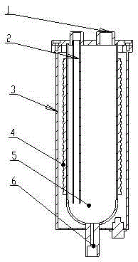
[0027] like figure 1 As shown, a high-efficiency refrigerating machine oil separation device includes a separation tank 5 . The separation tank 5 includes an elongated cylindrical tank body and a hemispherical tank bottom; the tank body and the tank bottom are welded or screwed. The height of the can body is 20-30 times its cross-sectional diameter. The tank height should be at least 1 meter.

[0028] The outer wall of the separation tank 5 is provided with a heating device 4, and the heating body of the heating device 4 is wound on the outer wall of the separation tank 5; the outer side of the separation tank 5 is detachably provided with a shield 3; and its accessories play a protective role; the shield 3 is located outside the heating device 4 .

[0029] The top of the separation tank 5 is provided with a refrigerant inlet 1, and the refrigerant inlet 1 is provided with a one-way valve. And the part of the bottom of the refrigerant inlet 1 extending into the separation ...

Embodiment 2

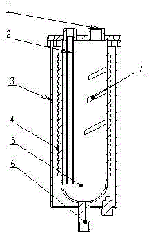
[0035] like figure 2 As shown, a high-efficiency refrigerating machine oil separation device includes a separation tank 5 . The separation tank 5 includes an elongated cylindrical tank body and a hemispherical tank bottom; the tank body and the tank bottom are welded or screwed. The height of the can body is 20-30 times its cross-sectional diameter. The tank height should be at least 1 meter.

[0036] The outer wall of the separation tank 5 is provided with a heating device 4, and the heating body of the heating device 4 is wound on the outer wall of the separation tank 5; the outer side of the separation tank 5 is detachably provided with a shield 3; and its accessories play a protective role; the shield 3 is located outside the heating device 4 .

[0037] The top of the separation tank 5 is provided with a refrigerant inlet 1, and the refrigerant inlet 1 is provided with a one-way valve. And the part of the bottom of the refrigerant inlet 1 extending into the separation...


PUM


Abstract

The invention discloses an efficient refrigerator oil separation device, and belongs to the technical field of refrigerant recovery and refrigerator oil separation. The efficient refrigerator oil separation device comprises a separation tank (5), wherein a heating device (4) is arranged on the outer wall of the separation tank (5); a refrigerant inlet (1) is formed in the top of the separation tank (5); a refrigerant outlet (2) is formed in the separation tank (5), and extends from the bottom of the separation tank (5) to the top of the separation tank (5); and a refrigerator oil outlet (6) is formed in the bottom of the separation tank (5). A gas-liquid mixture of refrigerant mixed with part refrigerator oil enters the separation tank from the refrigerant inlet in the top of the separation tank, and moves from top to bottom; under the effect of the heating device, the internal temperature of the separation tank is controlled in a range of 40-60 DEG C; and in the sinking process of the refrigerant gas-liquid mixture in the temperature range, the refrigerant is gasified, and the refrigerator oil is continuously kept in a liquid state to be separated out from the refrigerant.

Description

technical field [0001] The invention relates to the technical field of refrigerant recovery and refrigeration oil separation, in particular to a high-efficiency refrigeration oil separation device. Background technique [0002] The refrigerant recovery equipment is mainly used to recycle and reuse the refrigerant that has been filled in the air-conditioning system to prevent the refrigerant from being discharged into the air and causing environmental pollution. Refrigerator oil separation device is a key component of refrigerant recovery equipment. [0003] The refrigerant medium in the air-conditioning system and part of the refrigerating oil in the air-conditioning system are fused together. When the refrigerant recovery equipment recovers the refrigerant in the air-conditioning system, it will also recycle part of the refrigerating oil inside. In this way, in the process of recycling refrigerant It is necessary to separate the refrigeration oil, one is to ensure that the...

Claims


Application Information

Patent Timeline
Patent Type & Authority Applications(China)
IPC IPC(8): F25B43/02
CPCF25B43/02F25B2400/23
Inventor 葛桂新张吉全路兴堂
Owner JINAN CJR ELECTRICS CO LTD
Why Eureka
Try Eureka