
Inductance measuring apparatus for exhaust area of director guider blade

A technology for measuring exhaust area and inductance, applied in the field of aero-engines, can solve the problems of long measurement time and production cycle, unfavorable production and processing, cumbersome use, etc. Effect

Inactive Publication Date: 2016-02-24
SHENYANG LIMING AERO-ENGINE GROUP CORPORATION
View PDF6 Cites 5 Cited by
  • Summary
  • Abstract
  • Description
  • Claims
  • Application Information

AI Technical Summary

Problems solved by technology

There are many ways to measure the traditional exhaust area. One is the three-step measurement. Its characteristics are: the design and manufacture of measuring tools and standard parts are relatively simple, but it is cumbersome to use, and the reading of the dial indicator is biased. The value is converted into the actual value and then calculated to obtain the specific area value; another is to use a set of measuring tool standard parts to measure the upper and lower mounting plate measurement points, and design a set of measuring tool standard parts for every two sections of each section of the blade. More than two sets of accumulative measuring tools are required. Due to the design and manufacture of spatial angle surfaces, the design is very cumbersome and the manufacturing is very complicated. When using one set of measuring tools, only two cross-sections can be measured. The measurement time and production The cycle is very long, which is not conducive to production and processing

Method used


Image

  • Inductance measuring apparatus for exhaust area of director guider blade
  • Inductance measuring apparatus for exhaust area of director guider blade
  • Inductance measuring apparatus for exhaust area of director guider blade

Examples


Embodiment Construction

[0015] The present invention will be further described in detail below with reference to the accompanying drawings and specific embodiments.

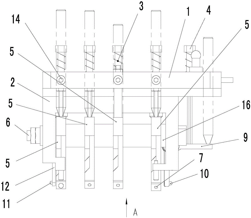
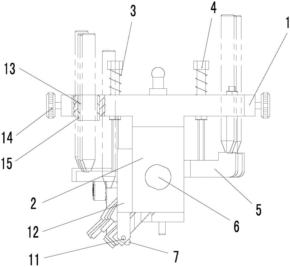
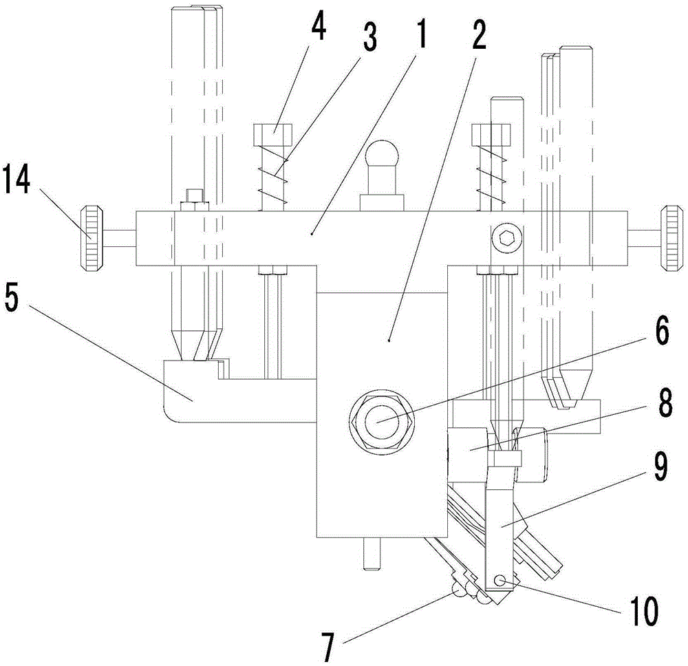
[0016] like Figure 1 to Figure 4 As shown, a guide vane exhaust area inductance measurement device includes a bracket 2, a bottom plate 1 is arranged on the upper part of the bracket 2, and a number of cross-section measuring levers 5 are arranged below the bottom plate 1; each section is correspondingly provided with two There are four cross-section measuring levers 5, in this embodiment, there are four cross-sections, so eight cross-section measuring levers 5 are correspondingly provided. The middle part of the section measuring lever 5 is arranged on the bracket 2 through the mandrel 6, and the section measuring lever 5 can rotate around the mandrel 6; , after the lower end of the limit screw 4 passes through the through hole, it is threadedly connected to the part between the upper end of the section measuring lever 5 and the mand...


PUM


Abstract

An inductance measuring apparatus for exhaust areas of director guider blades belongs to the technical field of aeroengines. The apparatus comprises a support. The upper portion of the support is provided with a base plate. Cross section measuring levers are disposed under the base plate. Every two cross section measuring levers correspond to one cross section. The middle portions of the cross section measuring levers are disposed on the support through a mandrel. The bottom end of each cross section measuring lever is provided with a contact. The base plate is equipped with through holes. The lower ends of limiting screws penetrate the through holes and then are in threaded connection with the cross section measuring levers. The base plate is also equipped with installing holes, which correspond to the upper ends of the cross section measuring levers. Locking screws are disposed on the base plate and positioned on the side of the installing holes. A positioning plate is disposed on one side of the support. The lower end of the positioning plate is equipped with a radial positioning pin. A radial measuring lever is disposed on the other side of the support. The middle portion of the radial measuring lever is connected to the support through a pin shaft. The limiting screws are in threaded connection with the radial measuring lever. The lower end of the radial measuring lever is provided with a measuring pin.

Description

technical field [0001] The invention belongs to the technical field of aero-engines, and in particular relates to an inductance measuring device for the exhaust area of ​​a guide vane, which is mainly applied to the measurement of the exhaust area of ​​aero-engine and a guide vane of a gas turbine. Background technique [0002] At present, the guide vanes are precision casting vanes, which are generally connected by three to six vanes, and the passage between two adjacent guide vanes is a complex curved surface. The measurement of the exhaust area of ​​the guide vane generally adopts the approximate trapezoidal measurement method—upper base, lower base and height, and the area of ​​the trapezoid is obtained through the measurement and calculation of these parameters. There are many traditional ways to measure the exhaust area. One is the three-step measurement, which is characterized by: the design and manufacture of measuring tools and standard parts are relatively simple, ...

Claims


Application Information

Patent Timeline
Patent Type & Authority Applications(China)
IPC IPC(8): G01B7/32
CPCG01B7/32
Inventor 陈佳慧孙玉林李有孙丽丽肖剑波
Owner SHENYANG LIMING AERO-ENGINE GROUP CORPORATION
Learn More