
Aligning correction device and method for space navigation detector ground calibration

A ground calibration and deviation correction device technology, which is applied in the field of space detectors, can solve the problems of low calibration accuracy and unsuitable calibration and correction of space navigation detectors, and achieve the effect of flexible operation

Active Publication Date: 2016-02-24
CHINA GREAT WALL IND CORP +1
View PDF6 Cites 17 Cited by
  • Summary
  • Abstract
  • Description
  • Claims
  • Application Information

AI Technical Summary

Problems solved by technology

[0004] The current detector and laser alignment method or device calibration accuracy is low, not suitable for calibration and correction of space navigation detectors

Method used


Image

  • Aligning correction device and method for space navigation detector ground calibration
  • Aligning correction device and method for space navigation detector ground calibration
  • Aligning correction device and method for space navigation detector ground calibration

Examples


Embodiment Construction

[0025] The present invention will be described in detail below with reference to the accompanying drawings and examples.

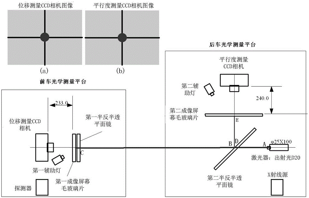
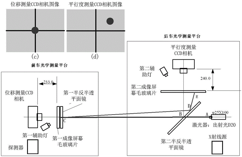
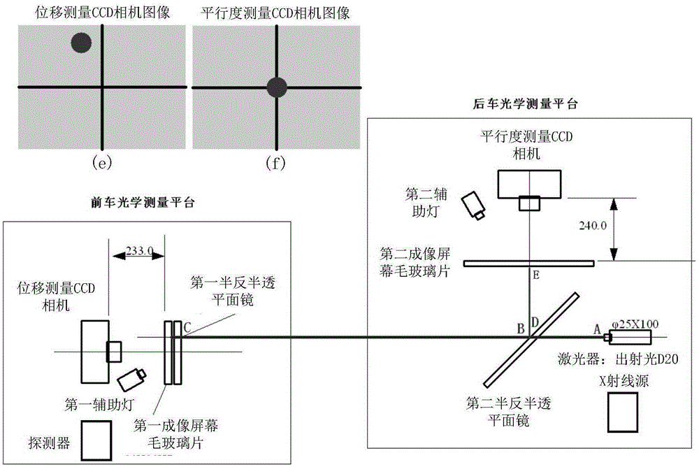
[0026] The invention provides an alignment correction device for ground calibration of a space navigation detector, such as figure 1 As shown, it includes the front vehicle optical measurement platform and the rear vehicle optical measurement platform, wherein the detector is fixedly installed on the front vehicle optical measurement platform, the X-ray source is fixedly installed on the rear vehicle optical measurement platform, and the front and rear vehicle optical measurement platforms Located at the front and rear ends of the vacuum beamline channel, the measurement platform is equipped with a displacement and attitude servo mechanism, which can realize the horizontal translation, height elevation and rotation of the measurement platform along its 3-dimensional coordinate axis. The optical measurement platforms of the front and rear cars are respectiv...


PUM


Abstract

The invention discloses an aligning correction device and method for space navigation detector ground calibration. Accuracy aligning of an X radiation source and a detector can be achieved through the device, and the parallel aligning error is less than 0.02 degree and the central aligning error is less than 1mm. The device comprises a front-vehicle optical measuring platform and a rear-vehicle optical measuring platform. A detector is fixedly installed on the front-vehicle optical measuring platform. An X radiation source is fixedly installed on the rear-vehicle optical measuring platform. The front-vehicle and rear-vehicle optical measuring platforms are located at front and rear ends of a vacuum beam line channel respectively. Firstly, parallelism aligning is carried out, the posture of the front-vehicle or rear-vehicle optical measuring platform is adjusted, and thus an image of a laser light spot is located at an imaging center of a parallelism measuring CCD camera; then height and horizontal displacement aligning is carried out, the posture of the front-vehicle or rear-vehicle optical measuring platform is adjusted, thus the image of the laser light spot is located at the imaging center of the displacement measuring CCD camera, and finally aligning of the X radiation source and the detector is achieved.

Description

technical field [0001] The invention relates to the technical field of space detectors, in particular to an alignment and deviation correction device and method for ground calibration of a space navigation detector. Background technique [0002] Space navigation detectors generally need to be calibrated on the ground first, but at present there are no specialized institutions and test devices for the calibration of space navigation detectors in China, and they are still in the exploratory stage. [0003] Relying on the major special project of the second-generation navigation of the final assembly "Pulsar Navigation Ground Test System", the 513 Institute has developed and completed the largest domestic large-scale vacuum test equipment with the most complete functions and the highest attitude adjustment accuracy-vacuum beamline channel. The vacuum beamline channel has an outer diameter of 2.1 meters and a total length of 17 meters, providing a vacuum working environment for ...

Claims


Application Information

Patent Timeline
Patent Type & Authority Applications(China)
IPC IPC(8): G01C21/24G01C25/00
CPCG01C21/24G01C25/00
Inventor 孙书坤邵飞史钰峰胡慧君纪春恒连剑宋娟
Owner CHINA GREAT WALL IND CORP
Learn More