
Demonstration model of roller straightening machine

A technology of straightening machine and model, applied in teaching models, educational appliances, instruments, etc., can solve the problem of not finding the teaching model of the roller straightening machine, and achieve light weight, good strength and rigidity, and reduce the space occupied. Effect

Inactive Publication Date: 2016-02-24
UNIV OF SCI & TECH LIAONING
View PDF5 Cites 1 Cited by
  • Summary
  • Abstract
  • Description
  • Claims
  • Application Information

AI Technical Summary

Problems solved by technology

At present, there are very few teaching models about steel rolling machinery in the classroom, especially no teaching model for roll leveling machines has been found.

Method used


Image

  • Demonstration model of roller straightening machine

Examples


Embodiment Construction

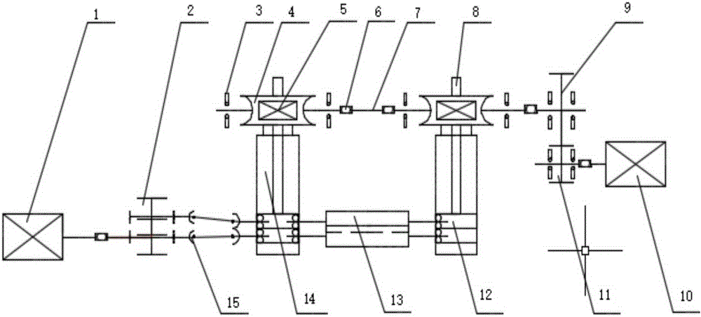
[0018] Such as figure 1 As shown, a teaching model of a roller straightening machine is composed of a main transmission system and a pressing system, wherein the main transmission system is composed of a main motor 1, a main transmission distribution gear 2, a universal joint shaft 15 and a straightening roller 13 , the main motor 1 adopts the xd-2d06-24 type DC geared motor, the power is 15W, the speed is 10rpm, bidirectional rotation, the main transmission distribution gear 2 is five, the universal joint shaft 15 is five, and the correction roller 13 is five , the main motor 1 is connected with a gear in the distribution gear 2, through the meshing of the remaining four gears, it drives five universal joint shafts 15, and then drives five correction rollers 13 to rotate, and each gear is installed on the rotating shaft There are bearings. The main motor 1 drives the main transmission distribution gear 2, and the main transmission distribution gear 2 drives the universal joi...


PUM


Abstract

The invention discloses a demonstration model of a roller straightening machine. The demonstration model is aimed at vividly demonstrating the working principles of a main drive system and a press-down system of a roller straightening machine. The model is formed by a main drive system and a press-down system. The main drive system comprises a main motor, main drive distribution gears, universal spindles and straightening rollers. The press-down system comprises bull gears, shaft couplings, worm gears, press-down screws, connection shafts, bearings, worms, pinions, a press-down motor, frames, straightening rollers and bearing pedestals, The mechanically-driven worm gears, worms, gears, screws and nuts are combined on the model quite smartly. In terms of the design of the press-down screws, the worm gears can serve as drive parts for secondary deceleration, and also can serve as press-down nuts for press-down adjustment. The model can be used for teaching of curriculums including steel rolling machinery, mechanical designs, mechanical principles, automation of metallurgy equipment and maintenance of mechanical equipment, and has wide application prospects.

Description

technical field [0001] The invention relates to a teaching model of a steel rolling machine, in particular to a teaching model of a roller straightening machine. Background technique: [0002] Existing straightening machine is made up of main transmission system and pressing down system two parts. Among them, the working principle of the main transmission system is that a main motor drives a plurality of vertically staggered and parallel-arranged correction rollers to move through the reducer, the gear seat and the universal joint. Its structure is complex and occupies a large space; The working principle of the system is that a motor simultaneously rotates the pressing nuts on the four columns through a two-stage worm gear reducer, and the four columns are also pressed screws and fixed on the frame. When adjusting the pressing, the column does not move, and the pressing nut moves together with the upper frame to realize the change of the upper and lower roll gaps. Because...

Claims


Application Information

Patent Timeline
Patent Type & Authority Applications(China)
IPC IPC(8): G09B25/02
CPCG09B25/02
Inventor 汪曦田甜刘冠霆赵忆文王睿聪王鑫昊
Owner UNIV OF SCI & TECH LIAONING
Learn More