Passive containment cooling system

A passive containment and cooling system technology, applied in cooling devices, nuclear power generation, reactors, etc., can solve the problems of shock resistance and thermal stress shock resistance, many penetrating parts, and limited capacity, so as to promote natural circulation capacity and heat dissipation. Effects of derived performance, fewer penetrations, good seismic performance and thermal stress shock resistance

Active Publication Date: 2016-02-24
CHINA NUCLEAR POWER ENG CO LTD
View PDF16 Cites 5 Cited by
  • Summary
  • Abstract
  • Description
  • Claims
  • Application Information

AI Technical Summary

Problems solved by technology

Some of these systems rely on the heat exchange surface of the inherent structure and have limited capacity, such as AP600&1000-PCS; some of them have certain hidden dangers in terms of earthquake resistance and thermal stress resistance due to their complex s

Method used


Image

  • Passive containment cooling system
  • Passive containment cooling system
  • Passive containment cooling system

Examples


Embodiment Construction

[0022] The specific implementation manners of the present invention will be further described in detail below in conjunction with the accompanying drawings.

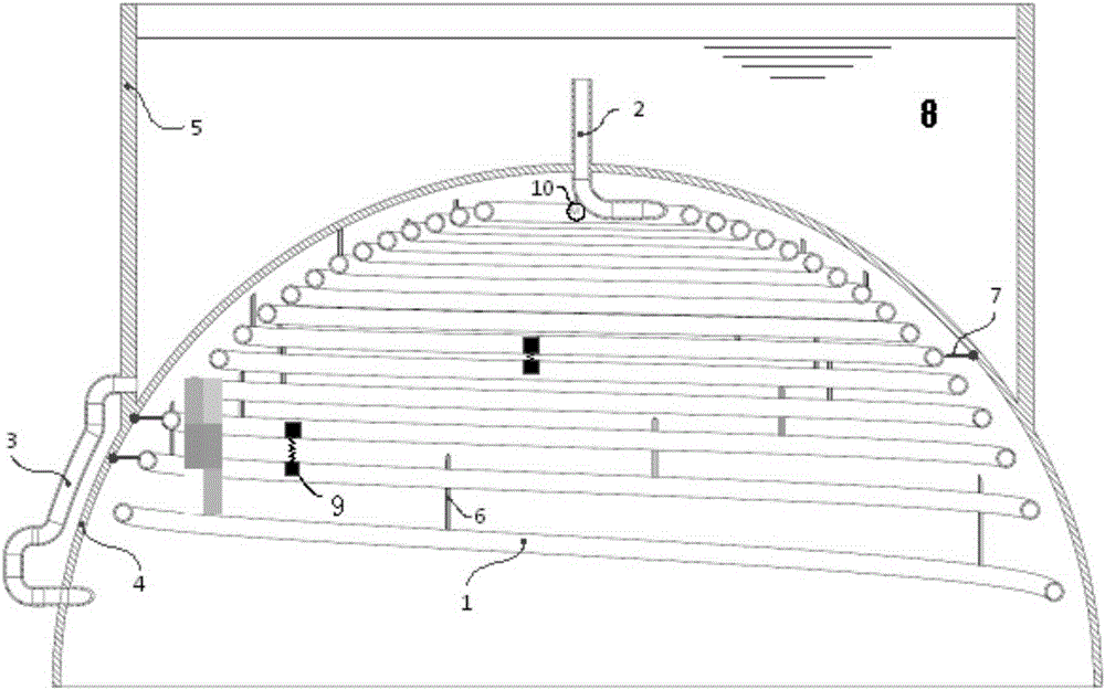
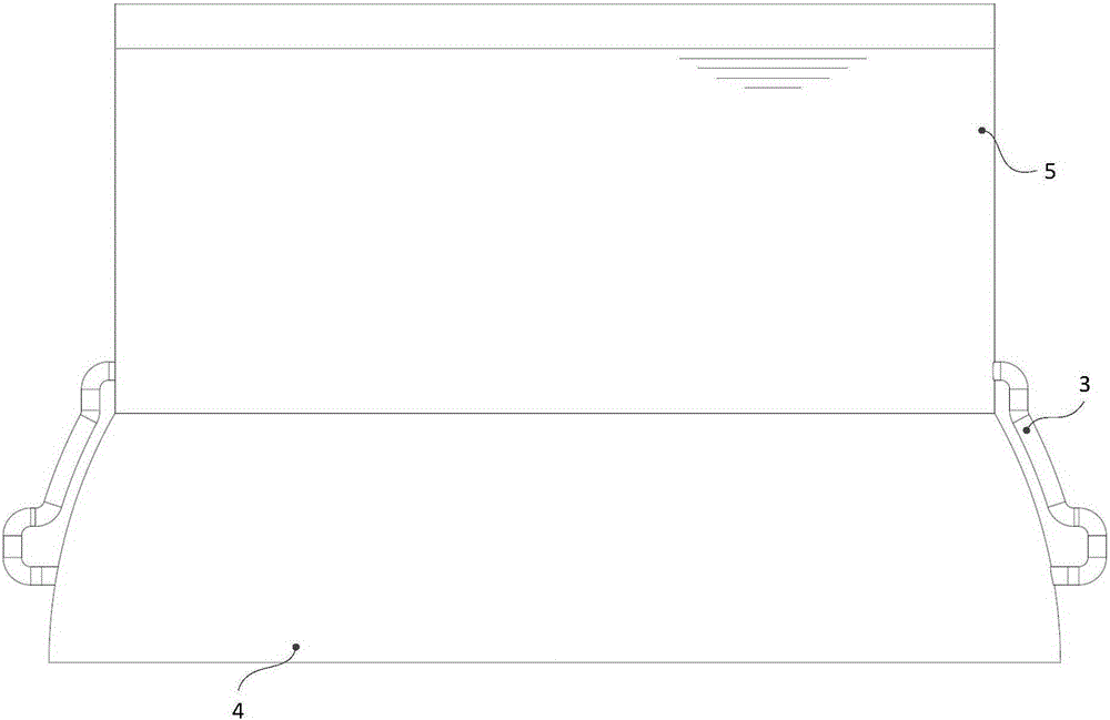
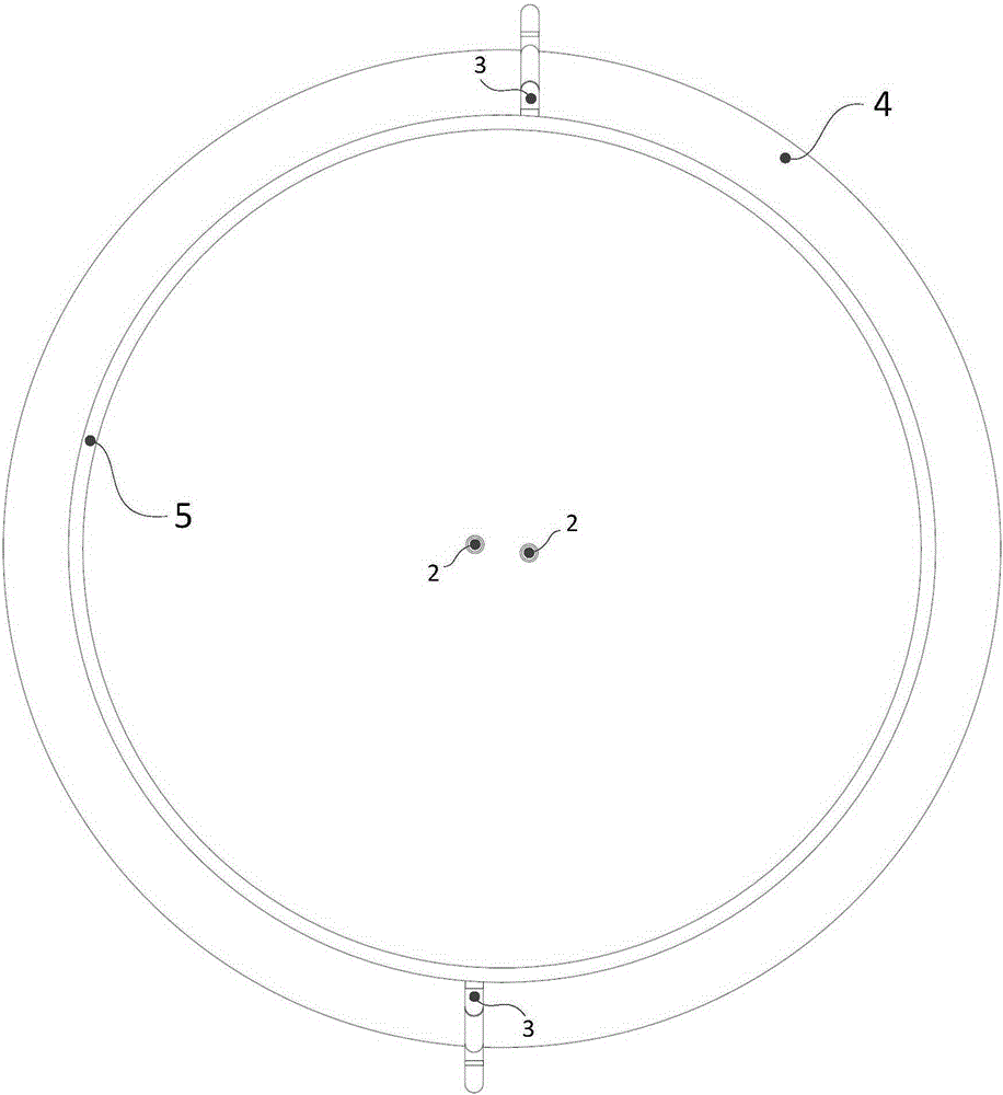
[0023] Such as figure 1 Shown is the passive containment cooling system provided by the present invention. The system includes a top-mounted water tank 5 fixed outside the containment and a spiral coil water cooling wall 1 arranged inside the containment. One end of the spiral coil water cooling wall 1 passes through The natural circulation inlet pipeline 3 is connected to the top water tank 5 , and the other end of the spiral coil water cooling wall is connected to the top water tank 5 through the natural circulation outlet pipeline 2 .

[0024] The spiral coil water wall 1 is arranged in the area of ​​the containment dome 4, and its outer contour surface fits the containment dome 4, and is connected to the containment dome 4 through the longitudinal rigid fixing member 6 and the transverse elastic fixing member 7 respe...


PUM


Abstract

The invention relates to a passive containment cooling system, which includes a top water tank (5) disposed outside a containment and a spiral coil water cooled wall (1) arranged in the containment, one end of the spiral coil water cooled wall (1) is connected to the top water tank (5) through a natural circulation inlet pipeline (3), the other end of the spiral coil water cooled wall (1) is in connection with the top water tank (5) through a natural circulation outlet pipeline (2), the spiral coil water cooled wall (1) is disposed in a containment dome (4) area and includes one or more spiral coils. The containment cooling system provided by the invention has the advantages of few containment penetration pieces, large heat exchange area, high heat exchange efficiency and good seismic performance, and also has a simple structure, thus providing higher inherent safety for nuclear reactor containments.

Description

technical field [0001] The invention belongs to a containment cooling system of a nuclear power plant, in particular to a passive containment cooling system. Background technique [0002] Most of the third-generation nuclear power systems have passive containment heat export systems (PCCS), such as: AP600&1000-PCS, ABWRII-PCCS, AHWR-PCCS, ESBWR-PCCS, SWR1000-PCCS, WWER640-PCCS and WWER1000-PCCS, etc. Some of these systems rely on the heat exchange surface of the inherent structure and have limited capacity, such as AP600&1000-PCS; some of them have certain hidden dangers in terms of earthquake resistance and thermal stress resistance because of the complex structure and many penetrating parts. The technical scheme of the present invention adopts the natural circulation mode of the water wall of the spiral coil to realize the heat export function of the containment, which is unprecedented in the design of similar systems. The patents involved in the above-mentioned passive c...

Claims


Application Information

Patent Timeline
IPC IPC(8): G21C15/18
CPCG21C15/18Y02E30/30
Inventor 韩旭封有才李春邹文重元一单
Owner CHINA NUCLEAR POWER ENG CO LTD
Why Eureka
Try Eureka