A waterproof capacitor installation device

An installation device, waterproof technology, applied in the direction of capacitors, electrical components, etc., can solve the problems of fragile studs, unable to prevent drying of terminals, capacitors falling off, etc., to achieve the effect of stable fixation and prevention of short circuit burning

Active Publication Date: 2018-10-23
GD MIDEA HEATING & VENTILATING EQUIP CO LTD +1
View PDF6 Cites 0 Cited by
  • Summary
  • Abstract
  • Description
  • Claims
  • Application Information

AI Technical Summary

Problems solved by technology

When installing the capacitor, the capacitor is clamped on the mounting plate through the capacitor snap ring. At this time, the force between the capacitor and the capacitor snap ring can ensure the positioning of the capacitor. Finally, the mounting plate is positioned on the electronic device to complete the capacitor. Assembling, the two supporting legs of this capacitor snap ring are very weak and easily deformed during assembly
Moisture is easy to rust, and it cannot prevent the terminals from drying out
Patent No. 201320281495.5 discloses a capacitor assembly device, which limits the degrees of freedom of the capacitor in front, back, left, and right through the resisting part and the elastic clamping part. There is a screw column on the side opposite to the limiting rib on the capacitor box. This patent has the following Disadvantages: 1. The reliability of capacitor fixing is low. Although it saves material costs, the capacitor may fall off after the relatively narrow elastic clamping part ages and fails in the electronically controlled high-temperature environment for a long time; the capacitor assembly device is only designed with One screw fixed position, the requirement for capacitor placement is high, you need to find the side of the box to assist positioning, otherwise the capacitor assembly device will rotate along the screw axis and cannot be positioned effectively; single screw positioning, transportation is unreliable, and the studs are fragile and damaged during assembly The latter part is directly scrapped and cannot be used; the capacitor terminal is not anti-condensate

Method used


Image

  • A waterproof capacitor installation device
  • A waterproof capacitor installation device
  • A waterproof capacitor installation device

Examples


Embodiment Construction

[0043] The principles and features of the present invention will be described below with reference to the accompanying drawings. The examples cited are only used to explain the present invention, and are not used to limit the scope of the present invention.

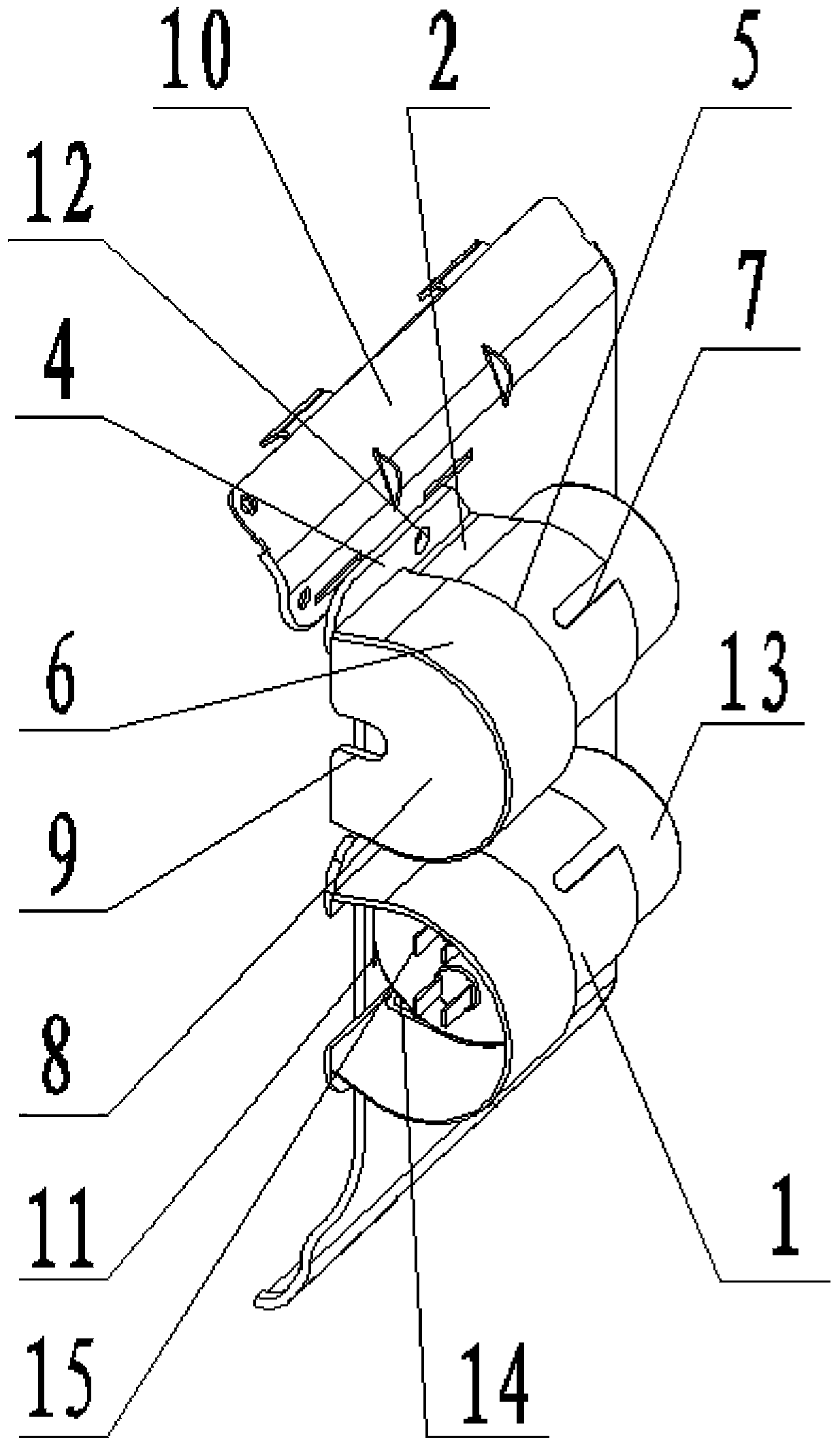
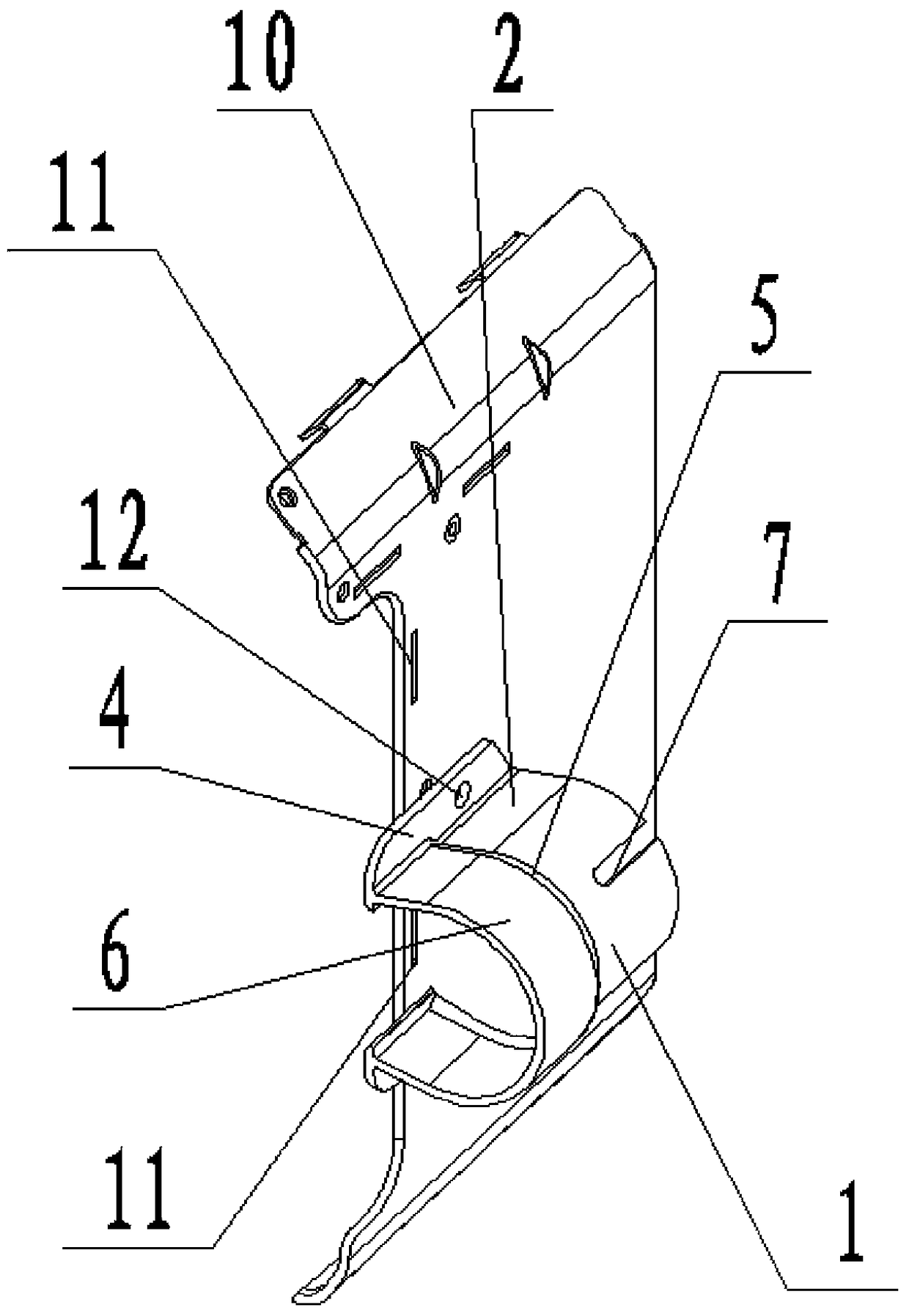
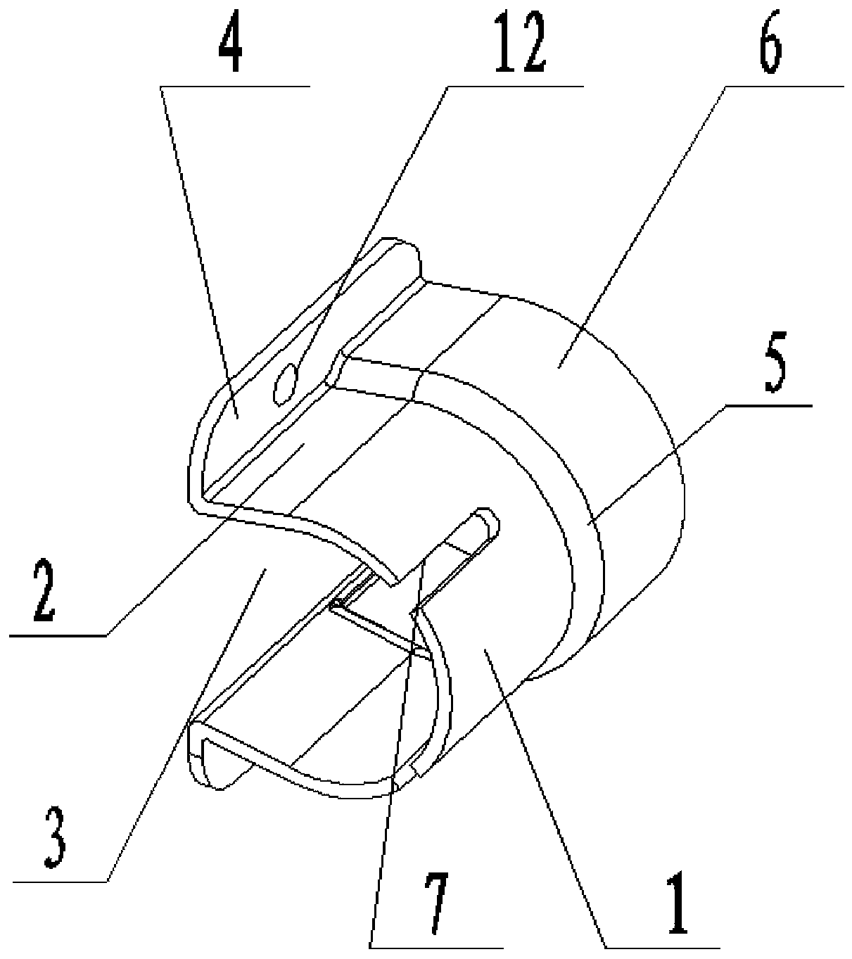
[0044] Such as figure 1 , figure 2 As shown, the present invention includes an elastic semi-cylindrical arc-shaped clamping surface 1 and clamping surfaces 2 provided on both sides of the circular arc-shaped clamping surface 1 in the axial direction. An assembly opening 3 is provided between the clamping surfaces 2, and an assembly edge 4 is provided on the sides of the two clamping surfaces 2 away from the arc-shaped clamping surface 1. The arc-shaped clamping surface 1 The middle part of the inner surface of the capacitor is provided with a ring-shaped capacitor end cover protrusion limiting portion 5, the ring-shaped capacitor end cover protrusion limiting portion 5 is coaxial with the arc-shaped clamping surface 1, the c...


PUM


Abstract

The invention relates to the technical field of capacitor installation equipment, and particularly relates to a waterproof capacitor installation device. The device comprises an elastic half-cylindrical arc chucking surface and clamping surfaces at two edges of the arc chucking surface in the axial direction, an assembly opening is formed between the two clamping surfaces, an assembly edge is formed on the side of each of the two clamping surfaces far from the arc chucking surface, an annular capacitor end cover protrusion limiting portion is formed on the inner surface of the arc chucking surface, the annular capacitor end cover protrusion limiting portion is coaxial with the arc chucking surface, one end of the arc chucking surface is a waterproof portion, and the capacitor end cover protrusion limiting portion presses against the waterproof portion. By adopting the device, a capacitor can be stably fixed; moreover, the waterproof portion can effectively shield and protect a capacitor connection terminal, and can prevent condensed water of a tubing system above from dropping and entering the connection terminal to cause short circuit and burning after the capacitor is assembled.

Description

Technical field [0001] The invention relates to the technical field of capacitor installation equipment, and in particular to a waterproof capacitor installation device. Background technique [0002] Capacitors are commonly used electronic components in electronic equipment. When installing electronic equipment, a capacitor assembly device is usually used to position the capacitor on the electronic equipment to ensure the normal operation of the electronic equipment. The positioning accuracy of the capacitor in the electronic device will have a greater impact on the work of the electronic device, so the requirements for the positioning accuracy of the capacitor are also increasing. [0003] In the traditional technology, the capacitor assembling device mainly includes a mounting board and a capacitor retaining ring arranged in the middle of the mounting board. When installing the capacitor, the entire capacitor is clamped on the mounting board through the capacitor retaining ring....

Claims


Application Information

Patent Timeline
Patent Type & Authority Patents(China)
IPC IPC(8): H01G2/02
Inventor 蔺勇智
Owner GD MIDEA HEATING & VENTILATING EQUIP CO LTD
Why Eureka
Try Eureka