
Communication method

A communication method and technology for communicating data, applied in electromagnetic wave transmission systems, optical fiber transmission, electrical components, etc., can solve the problems of high cost, high investment cost, and the inability of optical fibers to pass through, and achieve the effect of reducing construction work and communication costs.

Inactive Publication Date: 2016-02-24
DALIAN POWER SUPPLY COMPANY STATE GRID LIAONING ELECTRIC POWER +2
View PDF4 Cites 7 Cited by
  • Summary
  • Abstract
  • Description
  • Claims
  • Application Information

AI Technical Summary

Problems solved by technology

However, from the actual situation, for areas without reserved communication pipelines, the investment cost is relatively high and construction is difficult; for areas with reserved communication pipelines, 20%-30% of the pipelines have been blocked due to ground subsidence and other pipeline constructions. As a result, the optical fiber cannot pass through. It can be seen that the cost of networking with a single optical fiber communication system is relatively high

Method used


Image

  • Communication method
  • Communication method
  • Communication method

Examples


Embodiment 1

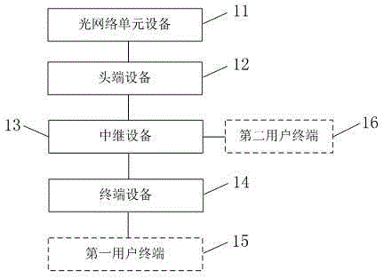
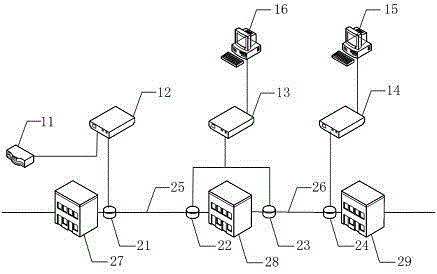
[0021] This embodiment provides a communication system, including: an optical network unit device 11, a head-end device 12, a relay device 13, and a terminal device 14. The optical network unit device 11 is connected to the head-end device 12 through a network cable, and the head-end device 12 passes The cable is connected to the relay device 13, and the relay device 13 is connected to the terminal device 14 through the cable;

[0022] Wherein, the optical network unit device 11 includes a first downlink signal processing unit and a first uplink signal processing unit, and the first downlink signal processing unit is used to receive the optical signal sent by the optical line terminal and convert it into a digital signal , sending a digital signal to the head-end device 12; the first uplink signal processing unit is used to receive the digital signal sent by the head-end device 12, convert it into an optical signal, and send the optical signal to the optical line terminal; the ...

Embodiment 2

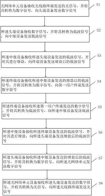
[0042] This embodiment provides a communication method, such as image 3 As shown, the method includes:

[0043] S1, the optical network unit device receives the optical signal sent by the optical line terminal, converts it into a digital signal, and sends the digital signal to the head-end device; the optical signal sent by the optical line terminal (OLT, optical line terminal) can be broadcast After the downlink communication data sent in the form of light wave is converted, the optical network unit device can send out a digital signal conforming to the IEEE802.3 standard, which is used to represent the downlink communication data.

[0044] S2, the head-end device receives the digital signal, converts it into a carrier signal, and sends the carrier signal to the relay device; the head-end device is connected to the optical network unit device through a network cable, and the head-end device may be equipped with The device of the carrier signal processing chip, such as the p...


PUM


Abstract

The invention provides a communication method. The downlink communication operation of the communication method includes: an optical network unit receives an optical signal sent from an optical line terminal, and converts the optical signal into a digital signal, and sends the digital signal to a head end device; the head end device receives the digital signal and converts the digital signal into a carrier signal and sends the carrier signal to a repeater device; the repeater device receives the carrier signal sent from the head end device, and performs gain for the carrier signal, and sends the carrier signal after gain to a terminal device; and the terminal device receives the carrier signal, sent from the repeater device, after gain, and converts the carrier signal after gain into a digital signal, and sends the digital signal to a first user terminal.

Description

technical field [0001] The invention relates to the field of data communication, in particular to a communication method. Background technique [0002] Distribution automation system is an important technical means to improve the production management level of distribution network and improve the reliability of power supply, and it is also one of the main contents of smart grid construction. The State Grid Corporation of China is comprehensively building a strong smart grid with UHV grid as the backbone and coordinated development of power grids at all levels, and featuring independent innovation and world-leading strong smart grid characterized by informatization, automation, and interaction. The smart grid is based on an open and interconnected information model, by loading system digital equipment and upgrading the grid network management system, it realizes the entire process of the power industry such as power generation, transmission, power supply, power consumption, c...

Claims


Application Information

Patent Timeline
Patent Type & Authority Applications(China)
IPC IPC(8): H04B3/54H04B3/56H04B10/25
CPCH04B3/54H04B3/56H04B10/25891
Inventor 栾敬钊于晓辉宋文峰杨万清刘冰金垒姜学朴牛明珠田晓明万涛
Owner DALIAN POWER SUPPLY COMPANY STATE GRID LIAONING ELECTRIC POWER
Learn More