
Oil-sludge separating device

A technology of oil sludge separation and oil tank, which is applied in the direction of quenching device, liquid separation, precipitation separation, etc., can solve the problems of high labor intensity, poor separation effect, and low work efficiency of operators, and achieve a simple structure, easy cleaning, and low cost. Effect

Inactive Publication Date: 2016-03-02
CHONGQING MEICHI TECH CO LTD
View PDF5 Cites 5 Cited by
  • Summary
  • Abstract
  • Description
  • Claims
  • Application Information

AI Technical Summary

Problems solved by technology

The existing sludge separation is realized by sedimentation by using the difference in density between sludges. Therefore, the separation effect is poor and the work efficiency is low, and the sludge in the separation device needs to be cleaned every day, which makes the operator labor intensive.

Method used


Image

  • Oil-sludge separating device
  • Oil-sludge separating device
  • Oil-sludge separating device

Examples


Embodiment

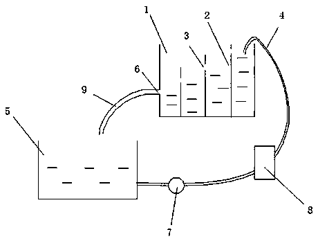
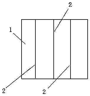
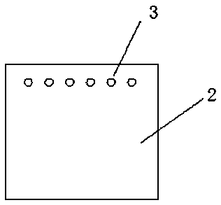
[0018] Embodiment, a kind of oil sludge separation device, see figure 1 , figure 2 with image 3 , including the oil tank 1, the oil tank 1 is provided with a vertical partition 2, the oil tank is divided into an oil inlet tank and an oil outlet tank through the partition board 2, an oil hole 3 is arranged on the partition board, and the oil inlet tank passes through the oil inlet pipe 4 and the quenching oil pool 5 The bottom of the oil outlet tank is connected to the top of the quenching oil pool 5 through the oil outlet hole 6, the position of the oil inlet pipe 4 is higher than the position of the oil hole 3, and the position of the oil outlet hole 6 is lower than the position of the oil hole 3.

[0019] There are three baffles 2 arranged in parallel, and the positions of the oil holes 3 on the three baffles 2 decrease sequentially from the oil inlet groove to the oil outlet groove.

[0020] An oil pump 7 and a heat exchanger 8 are arranged between the quenching oil poo...


PUM


Abstract

The invention discloses an oil-sludge separating device. The oil-sludge separating device comprises an oil tank; a plurality of separating plates are vertically arranged in the oil tank; the oil tank is divided into an oil inlet tank and an oil outlet tank by the separating plates; the separating plates are provided with oil holes; the oil outlet tank is provided with an oil outlet, and is connected with the upper part of an oil-quenching bath via the oil outlet; the oil inlet tank is connected with the bottom of the oil-quenching bath via an oil inlet pipe; the position of the oil inlet pipe is arranged to be higher than the position of the oil holes; and the position of the oil outlet is arranged to be lower than the position of the oil holes. The separating plates are used for dividing the oil tank; oil is subjected to a plurality of times of separating treatment, sludge in oil is completely precipitated at the bottom of the oil tank, water is precipitated at the lower layer, the purity of separated oil is high, and separating effect is improved.

Description

technical field [0001] The invention relates to a separation device, in particular to an oil sludge separation device. Background technique [0002] In the heat treatment process, the oil in the quenching oil pool is recycled after cooling and sludge separation. The existing sludge separation is achieved through sedimentation by utilizing the difference in density between sludges. Therefore, the separation effect is poor and the work efficiency is low, and the sludge in the separation device needs to be cleaned every day, which makes the operator labor intensive. Contents of the invention [0003] The purpose of the present invention is to provide an oil sludge separation device with good separation effect. [0004] The object of the present invention is achieved in this way, a kind of oily sludge separation device, comprises oil groove, is provided with vertical partition plate in oil groove and divides oil groove into oil inlet groove and oil outlet groove by separator,...

Claims


Application Information

Patent Timeline
Patent Type & Authority Applications(China)
IPC IPC(8): B01D17/028B01D21/02C21D1/63
CPCB01D17/0211B01D17/0214B01D21/0045B01D21/02C21D1/63
Inventor 杜祥全
Owner CHONGQING MEICHI TECH CO LTD
Learn More