Refraction type laser scanning device

A laser scanning device and laser technology, applied in laser welding equipment, welding equipment, metal processing equipment, etc., can solve the problems of complex control system, large volume, and difficult spatial positioning

Inactive Publication Date: 2016-03-02
HI TECH OPTOELECTRONICS
View PDF5 Cites 6 Cited by
  • Summary
  • Abstract
  • Description
  • Claims
  • Application Information

AI Technical Summary

Problems solved by technology

The disadvantages are large volume, difficult spatial positioni

Method used


Image

  • Refraction type laser scanning device
  • Refraction type laser scanning device
  • Refraction type laser scanning device

Examples


Embodiment Construction

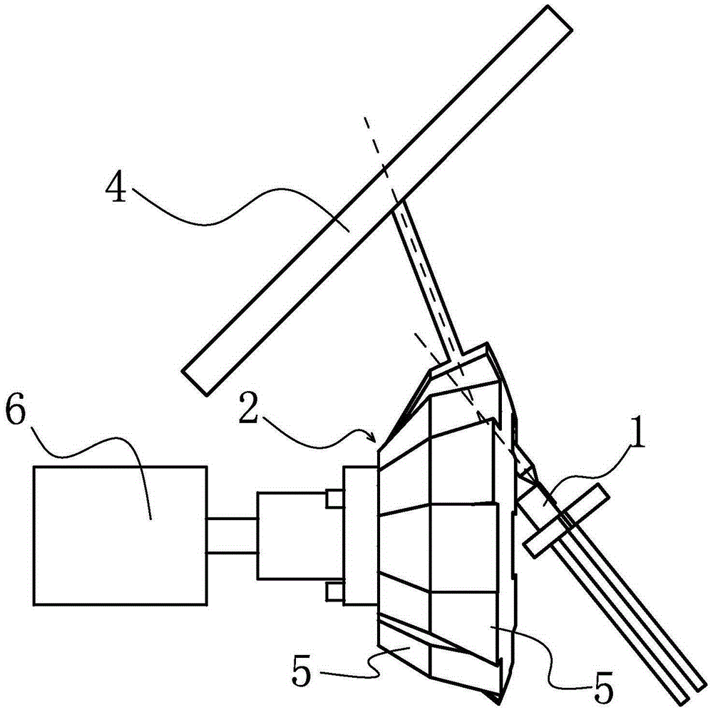
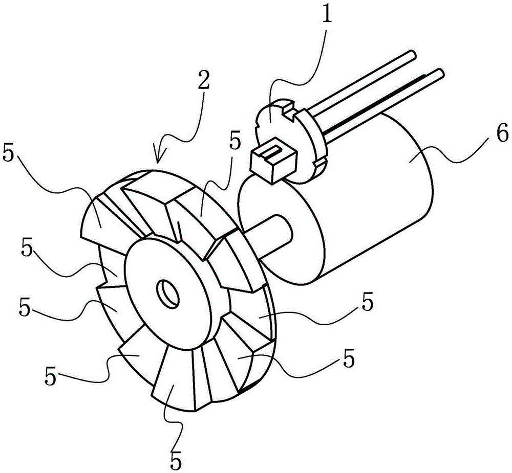
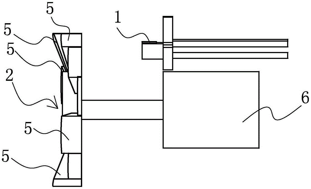
[0029] The following with attached Figure 1 to Figure 10 A refraction laser scanning device of the present invention will be further described in detail.

[0030] A refraction laser scanning device of the present invention, please refer to Figure 1 to Figure 10 , including a semiconductor laser emission source 1 and a rotatable prism assembly 2, the rear end of the prism assembly 2 is connected to a rotation drive device 6, and the rotation drive device 6 and the semiconductor laser emission source 1 are respectively located in the prism The front and rear sides of the assembly 2 are located on the same side or on both sides respectively. The prism assembly 2 includes at least two prism units equally divided, and each of the prism units is a separate light-transmitting prism element 5. The direction of the laser light emitted by the semiconductor laser emitting source 1 is in the same direction or has an included angle with the axis direction of the rotary drive device 6 , ...


PUM


Abstract

The invention discloses a refraction type laser scanning device. The refraction type laser scanning device comprises a semiconductor laser emitting source and a rotatable prism assembling unit. The rear end of the prism assembling unit is connected with a rotation driving device, and the rotation driving device and the semiconductor laser emitting source are located on the same side of the front side face and the rear side face of the prism assembling unit respectively or located on the two sides respectively. The prism assembling unit comprises at least two prism units which are equant. Each prism unit is an independent light-transmitting prism element. The direction of lasers emitted by the semiconductor laser emitting source and the axial direction of the rotation driving device are the same or an included angle is formed between the directions. The vertex angles of the adjacent prism elements are different. The refraction type laser scanning device is simple in structure, the light source and the driving device can be placed on the same side, the overall size is small, the occupied space is small, the production process is simple, control is easy, production cost is low, positioning is simple, reliability is high, and operation is convenient.

Description

technical field [0001] The invention relates to a laser scanning device, in particular to a refraction laser scanning device which is mainly used in laser medical treatment and laser beauty treatment. Background technique [0002] At present, with the rapid development of laser technology, lasers of various wavelengths emerge in an endless stream, and more light sources are used in the human health and beauty industries. Using the thermal characteristics of light and the selective absorption characteristics of human tissues for light wavelengths, targeted Change the internal tissue structure and performance of the human body to achieve the purpose of beauty, physical therapy and health. [0003] To act light on human tissue, the technology widely used at present is to scan with a reflective laser galvanometer. The principle is to install the reflector on the shaft of the swing motor, place two sets of motors perpendicular to each other, and the two sets of electrodes are not...

Claims


Application Information

Patent Timeline
IPC IPC(8): B23K26/082
Inventor 孙海东宋金星刘迪
Owner HI TECH OPTOELECTRONICS
Why Eureka
Try Eureka