Hand tool

A technology of hand-held machine tools and driven shafts, which is applied in the direction of manufacturing tools, portable drilling machines, portable motorized devices, etc. It can solve the problems that the locking mechanism does not allow one-handed replacement, and the tools cannot be used in hand-held machine tools.

Active Publication Date: 2016-03-02
ROBERT BOSCH GMBH
View PDF3 Cites 3 Cited by
  • Summary
  • Abstract
  • Description
  • Claims
  • Application Information

AI Technical Summary

Problems solved by technology

[0003] A disadvantage of the prior art is that the manually actuated locking mechanism does not allow a one-handed tool change and that the known locking devices require a relatively large i...

Method used


Image

  • Hand tool
  • Hand tool
  • Hand tool

Examples


Embodiment Construction

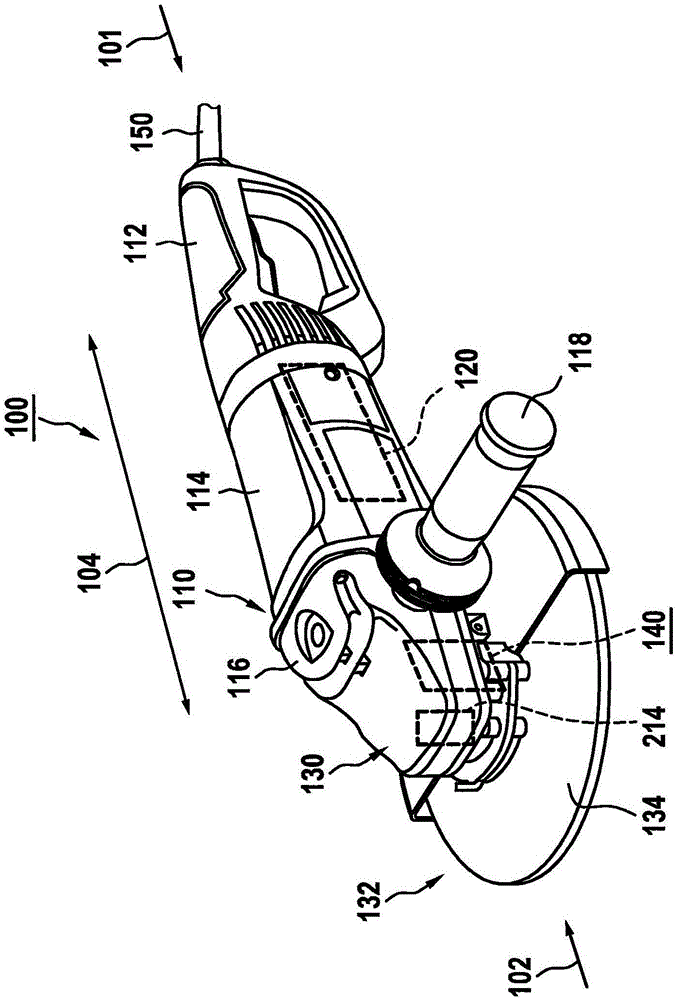
[0035] figure 1 A hand-held power tool 100 designed as an angle grinder is shown, which has a locking device 140 according to one embodiment of the invention. However, it should also be pointed out that hand-held power tool 100 is designed as an angle grinder only by way of example and is not intended to limit the invention. On the contrary, it can also generally be used in hand-held power tools, in particular portable power tools, which are equipped or can be equipped with locking device 140 according to the invention. In the context of the present invention, a "portable electric tool" is to be understood as an electric tool that can be transported by a user without a transport mechanism. In this case, locking device 140 can preferably be integrated in any electrical tool in a modular and / or exchangeable manner, for example via a plug connection.

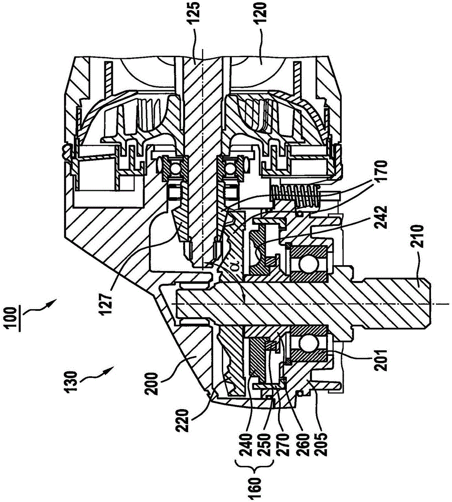
[0036] A drive motor 120 for driving a driven component 130 is preferably arranged in housing 110 assigned to angle grinder 100...


PUM


Abstract

A hand tool has a housing. A driving shaft driven by a driving motor and a driven shaft driven by the driving shaft are arranged in the housing at least in sections. The driven shaft is equipped with a locking device which is constructed to be used for preventing the driven shaft from rotatably moving at least indirectly when torque is imposed on the driven shaft which is in the static state. The locking device is provided with at least one locking element which is capable of axially moving relative to the driven shaft. The locking elements are constructed to be used for locking the rotational movement of the driven shaft when the driven shaft is not driven in a first axial operation position, and permitting the rotational movement of the driven shaft when the driven shaft is driven in a second axial operation position. The locking device is constructed to be used for allowing the axially movable locking elements to transit to the second axial operation position from the first axial operation position when the driving shaft carries out driving.

Description

technical field [0001] The invention relates to a hand-held power tool having a housing in which a drive shaft drivable by a drive motor and an output shaft drivable by the drive shaft are arranged at least in sections, wherein A locking device is assigned to the driven shaft, which is designed to at least indirectly prevent a rotational movement of the driven shaft when a torque is applied to the driven shaft in the stationary state of the drive shaft. . Background technique [0002] On the one hand, the prior art discloses hand-held power tools, such as angle grinders or drills, in which the drive shaft or the output shaft must be unlocked by means of a locking mechanism manually actuatable by the operator. transition between the locked state and the dead state, or vice versa. Angle grinders are known, for example, in which the output shaft is locked and released via a button. In addition, hand-held power tools with a locking device, the so-called "automatic spindle loc...

Claims


Application Information

Patent Timeline
IPC IPC(8): B25F5/00B23B45/00B24B23/02
CPCB24B23/022B24B23/028B25F5/001
Inventor M·施佩尔M·卢茨F·埃森魏因
Owner ROBERT BOSCH GMBH
Why Eureka
Try Eureka