
Anchor mouth and profile generation method thereof

An anchor lip and contour technology, applied in the direction of ships, etc., can solve the problems of anchor rod and anchor claw breakage, anchor failure, stuck, etc., to reduce costs, facilitate welding, and save materials.

Inactive Publication Date: 2016-03-02
JIANGSU UNIV OF SCI & TECH
View PDF9 Cites 7 Cited by
  • Summary
  • Abstract
  • Description
  • Claims
  • Application Information

AI Technical Summary

Problems solved by technology

However, the track of the anchor lip of the fixed track structure is difficult to design and process, and the precision is low. It often happens that the anchor handle cannot enter the track smoothly, resulting in the phenomenon that the anchor fluke is stuck with the outer plate (anchor table) during the turning process, resulting in At the same time, the anchor lip of the traditional spiral structure, as we all know, Xingang Shipbuilding Heavy Industry has disclosed a patent for a spiral anchor lip (publication number: CN202765234U). On the basis of the traditional anchor lip, the inner contour surface is designed as a spiral , forming a spiral track, so that the anchor sticks close to the inner contour surface of the spiral and rises, prompting the anchor claws to turn upwards to realize anchor pulling
However, the traditional helical structure cannot guarantee the stability when the fluke flips and rises, resulting in the breakage of the bolt and the fluke, and the specific position of the fluke at the anchor lip at the end of the flip and rise cannot be found, and it is difficult to design and manufacture ,higher cost

Method used


Image

  • Anchor mouth and profile generation method thereof
  • Anchor mouth and profile generation method thereof
  • Anchor mouth and profile generation method thereof

Examples


Embodiment Construction

[0037] The present invention will be further described below in conjunction with the accompanying drawings.

[0038] Taking the shell shape of the snail shell in nature as the research object, find a logarithmic spiral equation r=a·e b·θ (where a=e c , c is the integral constant) to satisfy the shape curve of the spiral shell, so 100 points were taken in 50 shells with different shells, and the ORGIN software was used to connect the points into a line, and fit the logarithmic spiral, Get the bionic helix equation r=1.4e 0.12θ . The bionic helical anchor lip of the present invention is designed according to the bionic helical line equation and referring to the anchor lip design specification.

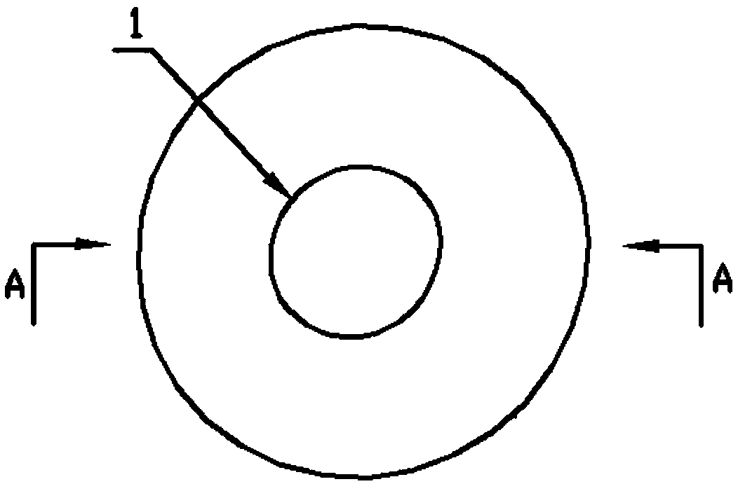
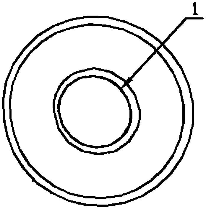
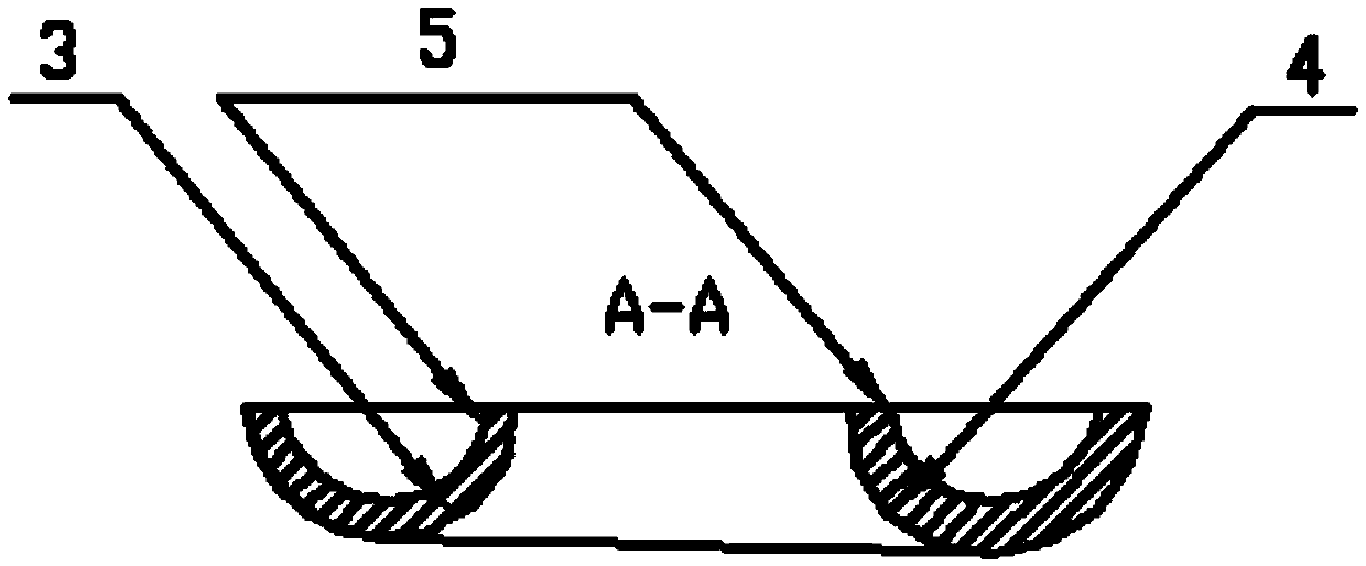
[0039] Such as Figure 1 to Figure 4 As shown, a method for generating the anchor lip contour of the present invention includes determining the inner contour line 1 of the anchor lip, the top contour line 2 of the anchor lip, the bottom contour line 3 of the anchor lip, the internal ...


PUM


Abstract

The invention discloses a bionic spiral anchor mouth profile generation method. The method comprises determination of an anchor mouth inner profile line, an anchor mouth top end profile line, an anchor mouth bottom end profile line, an anchor mouth inner notch profile line and an anchor mouth inner notch rotating center trajectory line; the anchor mouth inner profile line is scanned along curved lines of the anchor mouth top end profile line and the anchor mouth bottom end profile line to obtain an anchor mouth inner profile surface; the anchor mouth top end profile line and the anchor mouth bottom end profile line respectively rotate by 90 degrees in the left-right direction along the anchor mouth inner profile surface to perform the variable section scanning, after profiles obtained by scanning are joined, an anchor mouth external profile is obtained; and then, the anchor mouth inner notch profile line rotates by 360 degrees along the anchor mouth inner notch rotating center trajectory line to obtain an anchor mouth internal profile. The anchor mouth internal profile surface has an excellent spiral structure to facilitate to design and manufacture an anchor mouth, and in particular, to provide theoretical basis for the casting process; and the internal of an anchor mouth is grooved to facilitate to weld the anchor mouth and an anchor table surface.

Description

technical field [0001] The invention relates to a ship component, in particular to an anchor lip and a contour generating method thereof. Background technique [0002] With the development of modern shipbuilding, while improving the various performances of ships, in order to increase the capacity of the cargo hold of the hull, the capacity of the fore and aft peaks is correspondingly shortened. This brings great difficulties to the anchor test of the hull and the mooring arrangement of the deck. Especially in order to increase the speed of the ship, the draft part of the bow is designed as a bulbous nose. The anchor lip, as an important part of the hull, plays a vital role in the process of mooring and anchoring. Its main function is to prevent friction between the anchor chain and the anchor platform; the second is to use the height of the anchor lip and the inclination of the upper surface After the anchor lifting is completed, the anchor crown, the anchor lip, and the a...

Claims


Application Information

Patent Timeline
Patent Type & Authority Applications(China)
IPC IPC(8): B63B21/14
CPCB63B21/14
Inventor 张建高泽唐文献晏飞苏世杰齐继阳孙泽王震
Owner JIANGSU UNIV OF SCI & TECH
Learn More