Paper transferring and suction air path structure and operating method thereof

A technology of suction air path and working method, which is applied in the direction of object supply, pile separation, thin material processing, etc., can solve the problems of poor reliability, large hose wear, and cumbersome problems, and achieve high reliability and durability, and simple structure , reduce the effect of support points

Active Publication Date: 2016-03-02
MASTERWORK GROUP CO LTD
View PDF5 Cites 0 Cited by
  • Summary
  • Abstract
  • Description
  • Claims
  • Application Information

AI Technical Summary

Problems solved by technology

There are the following technical problems in the paper delivery suction air circuit: 1. The hose is deformed to adapt to the movement of the paper delivery, which causes great wear and tear on the hose, the hose is not durable, and has poor reliability
2. The hose cannot support the feeder board, which makes the whole result of the feeder board very complicated and cumbersome, and a support frame needs to be specially designed under the feeder board

Method used


Image

  • Paper transferring and suction air path structure and operating method thereof

Examples


Embodiment

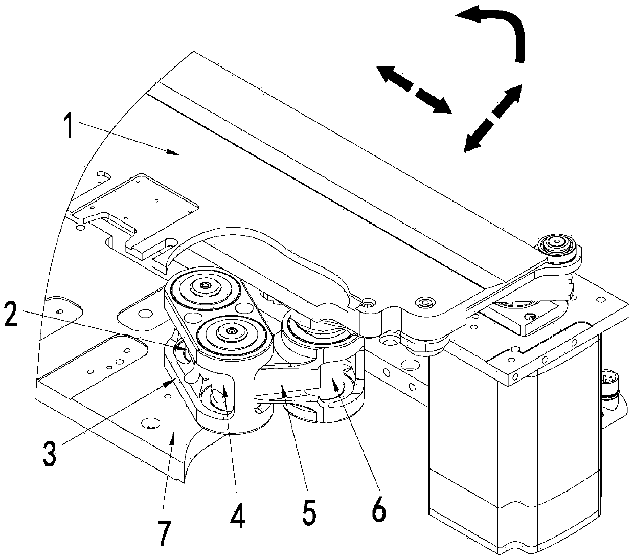
[0015] Embodiment: a kind of paper-passing suction air path structure (see figure 1 ), which is characterized in that it includes a paper passer plate 1, a connecting rod support mechanism and a bottom plate 7; the two ends of the link support mechanism are respectively hinged with the paper passer plate 1 and the bottom plate 7; the paper passer plate 1, The connecting rod support mechanism and the bottom plate 7 are provided with vent holes communicating with each other.

[0016] The connecting rod support mechanism includes a fixed mandrel I2, a connecting rod I3, a movable mandrel 4, a connecting rod II5 and a fixed mandrel II6; the fixed mandrel I2 is fixed on the bottom plate 7; The paper board 1 is fixedly connected; one end of the connecting rod I3 forms a rotatable hinge with the fixed mandrel I2 through a pair of bearings, and the other end of the connecting rod I3 forms a rotatable hinge with the movable mandrel 4 through a bearing; the connecting rod II5 One end i...


PUM


Abstract

The invention relates to a paper transferring and suction air path structure. The paper transferring and suction air path structure is characterized by comprising a paper transferring device board, a connecting rod supporting mechanism and a base board, wherein the paper transferring device board and the base board are respectively hinged to both ends of the connecting rod supporting mechanism, and air holes which are mutually communicated are respectively formed in the paper transferring device board, the connecting rod supporting mechanism and the base board. According to an operating method, when paper on a paper transferring device needs to be corrected, the paper transferring device board moves; when the paper transferring device board moves, the connecting rod supporting mechanism moves, air passes through the air hole in the base board and enters the connecting rod supporting mechanism, and finally, the air flows from the paper transferring device board, so that the paper is adsorbed. The paper transferring and suction air path structure has the advantages that a mechanical connecting rod and a hinge are adopted to realize the communication of an air path, so that the need of correction rotation of the paper transferring device board is guaranteed, and the communication of the air path in any position is realized; the structure is simple, and additionally, the reliability and the durability are high by adopting mechanical parts to connect; the connecting rod and a mandrel are adopted by the device, so that the smoothness of the air path is guaranteed, additionally, the effect of supporting the paper transferring device board is achieved, and the number of support points of the paper transferring device board is reduced.

Description

(1) Technical field: [0001] The invention is applicable to the field of printing machinery and equipment, and is particularly suitable for die-cutting machines and die ironing machines, that is, a paper-transferring suction air circuit structure and a working method thereof. (two) background technology: [0002] The paper delivery suction air circuit is installed on the paper feeding part of the die-cutting machine to fix or assist the adjustment of the paper delivery board to complete the paper delivery process. [0003] The suction air path of the paper transfer in the prior art is mostly connected by hoses. Its working principle is that a row of hoses are arranged under the paper transfer board in sequence. When paper passes through the paper transfer board, the hoses rise, Suction the paper and then move it down, the paper goes forward. The whole process is based on the deformation of the hose to adapt to the movement of the paper. There are several technical problems ...

Claims


Application Information

Patent Timeline
IPC IPC(8): B65H5/22
CPCB65H5/222B65H2301/44336
Inventor 首云飞乔龙
Owner MASTERWORK GROUP CO LTD
Why Eureka
Try Eureka