Ramming clamp and method for cooling wall expansion gap

A stave and expansion joint technology, applied in the direction of cooling devices, etc., can solve the problems of reducing the life of the blast furnace hearth, affecting the service life of the blast furnace hearth, and affecting the cooling intensity, so as to avoid gas blowing in the stave, improve the ramming method, The effect of guaranteeing the service life

Active Publication Date: 2016-03-02
BAOSHAN IRON & STEEL CO LTD
View PDF6 Cites 4 Cited by
  • Summary
  • Abstract
  • Description
  • Claims
  • Application Information

AI Technical Summary

Problems solved by technology

[0003] At present, the expansion joints of blast furnace hearth staves are rammed with thin iron sheets and fixed with lead wires to achieve this purpose. Due to the flexibility of the lead wire, it is easy to stretch, elongate and deform during the ramming process, so that gaps appear in the closed part, causing the ramming material to scatter and the compactness cannot meet the requirements. In severe cases, the wire breaks and cannot meet the ramming quality requirements. Thus affecting the service life of blast furnace hearth
In addition, since the cooling wall is thicker (that is, the depth of the expansion joint is relatively deep), generally up to 160mm, and the distance between two adjacent cooling walls is relatively short (that is, the width of the expansion joint is small), so when the filler in the expansion joint is rammed , can not guarantee the compactness and uniformity of the ramming, thereby reducing the thermal conductivity of the ramming material, which will cause the blow-by of the cooling wall of the blast furnace due to poor ramming compactness, affect the cooling intensity, and reduce the life of the blast furnace hearth

Method used


Image

  • Ramming clamp and method for cooling wall expansion gap
  • Ramming clamp and method for cooling wall expansion gap
  • Ramming clamp and method for cooling wall expansion gap

Examples


Embodiment Construction

[0031] The specific implementation manners of the present invention will be described in detail below in conjunction with the accompanying drawings of the embodiments.

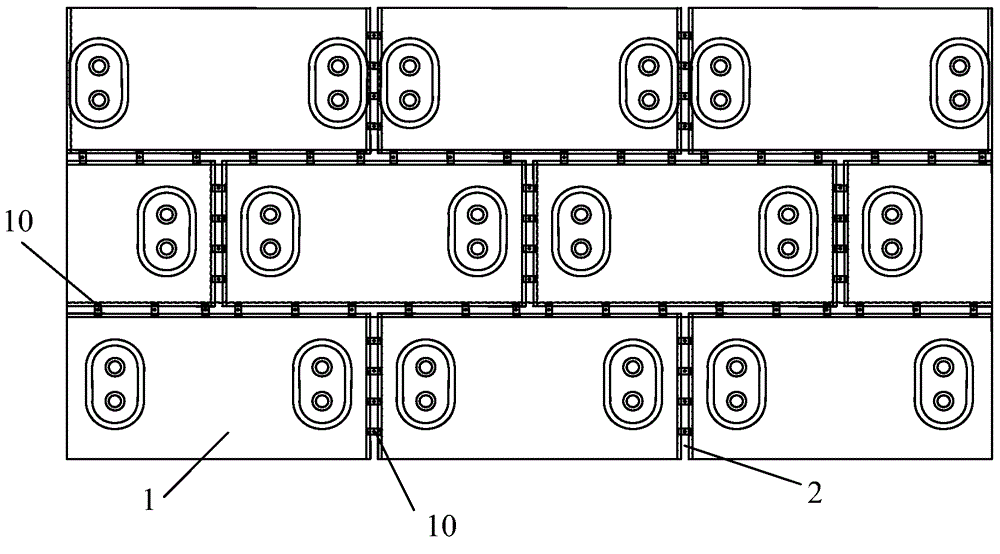
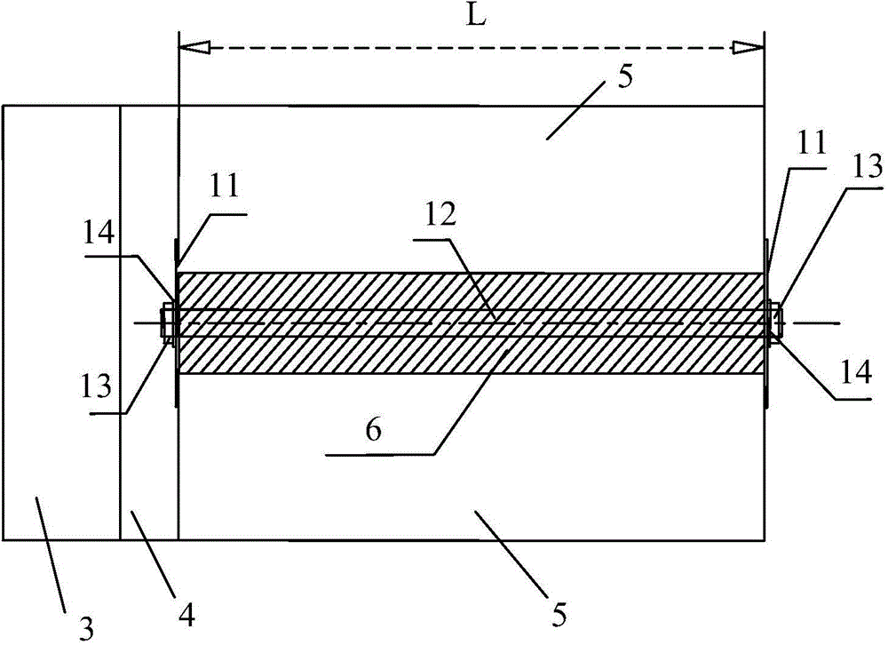
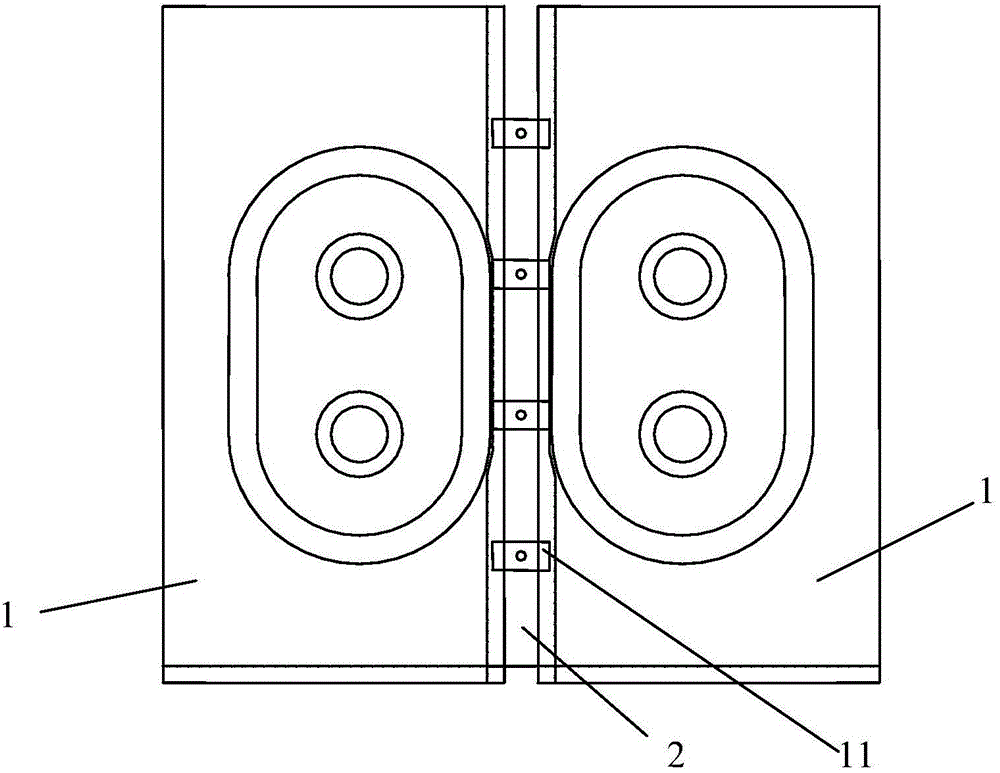
[0032] see figure 1 and figure 2 , the stave expansion joint ramming fixture 100 of the present invention is respectively arranged at intervals in the expansion joints 2 between the horizontal and vertical adjacent staves 1, and each ramming fixture includes a pair of steel baffle plates 11, a screw rod 12. A pair of fastening nuts 13, the length of the two baffles 11 is greater than the width of the expansion joint 2, and they are respectively located outside the two ends of the expansion joint 2, and overlapped with the outer walls of the two adjacent staves 1, the baffles 11 There are also screw holes on the top, the two ends of the screw rod 12 pass through the expansion joint 2 along the length direction of the expansion joint 2, and respectively pass through the screw holes of the baffle plate 11, and ...


PUM

PropertyMeasurementUnit
thicknessaaaaaaaaaa

Abstract

The invention discloses a ramming clamp for a cooling wall expansion gap. The ramming clamp is composed of steel plates, a screw rod, fastening nuts, spacers and other assemblies. The whole clamp has enough rigidity and strength and is tightened and fixed through the nuts, it can be avoided that baffles move due to strength generated in the ramming process, carbon materials can enter a cooling surface, and the requirement for ramming compactness and uniformity in the ramming process can be met; and furthermore, the structure is simple, fixation is facilitated through the threaded manner, exposed parts can be quickly cut and removed after ramming is finished, and a brick lining in the hot surface of the cooling wall can be built without influences. The invention further discloses a ramming method for the cooling wall expansion gap. The ramming method is improved by arranging ramming clamps and carrying out layered multi-time ramming, the uniformity of rammed materials can be improved, and thus the heat conductivity of the rammed material is ensured; and the phenomena that the cooling wall of a blast furnace leaks air due to poor ramming compactness, and the cooling strength is affected are avoided, and the service life of a hearth of the blast furnace is ensured.

Description

technical field [0001] The invention relates to the installation technology of a blast furnace hearth stave, in particular to a ramming fixture and a ramming method for an expansion joint of a stave. Background technique [0002] The hearth of the blast furnace is the part of the blast furnace that stores molten iron and slag. Its structure is generally divided into furnace skin, carbon ramming material, stave, carbon brick, and clay protective brick from the outside to the inside. The stave is basically a cuboid structure, and it needs to be arranged in a circular distribution in the blast furnace. Therefore, there will inevitably be cuboid or trapezoidal voids in the shape of a cuboid or trapezoidal platform (called the expansion joint void of the stave) during the installation of the blast furnace hearth stave. It affects the life of the blast furnace hearth and directly determines the life of the blast furnace. For this reason, when a blast furnace is newly built or ove...

Claims


Application Information

Patent Timeline
Patent Type & Authority Applications(China)
IPC IPC(8): C21B7/10
Inventor 缪伟良赵思杰
Owner BAOSHAN IRON & STEEL CO LTD
Why Eureka
Try Eureka