Heat engine

a technology of heat engine and expansion chamber, which is applied in the direction of liquid fuel engine, machine/engine, rotary/oscillating piston pump components, etc., can solve the problems of lower combustion temperature, lower pollution production rate, and high combustion efficiency, and achieves a small expansion chamber volume and a long driving force. , the effect of minimizing the volume in each chamber

Active Publication Date: 2015-03-17
DAVIS BRIAN
View PDF48 Cites 2 Cited by
  • Summary
  • Abstract
  • Description
  • Claims
  • Application Information

AI Technical Summary

Benefits of technology

[0038]According to one advantage of the present invention, the engine utilizes an elongated driving force due to opening of a valve when one of three apexes passes a prior exhaust port and the expansion chamber volume is small. The faces of the rotor are smooth and undished in order to minimize the volume in each chamber when the valve first opens.
[0039]According to another advantage of the present invention, the input valve can be closed at the appropriate timing whereby pressure in the expansion chamber and the pressure in the system outside of the expansion chamber will be approximately equal when the rotor leading apex passes the exhaust port. In this regard, the efficiency of the expansion phase is maximized because all of the energy is utilized as the pressures are equalized when the system opens to the exhaust.
[0040]According to further advantage of the present invention, the use of valves prevents blow-by in the system. Blow-by would otherwise occur in a system having three apexes of a triangular rotor and two inlets and two exhaust ports spaced about an engine housing since at times in the revolution of the rotor a chamber would be open to both an inlet and an exhaust port at the same time. Using a valve prevents this occurrence from happening.
[0041]According to a still further advantage of the present invention, fixed gates are provided to decrease expansion chamber volume (start of the expansion) and also to increase the mechanical advantage of the rotor during the expansion (the portion of driving force about one side of a rotor as the rotor orbits about the housing center point). The side of the rotor upon which driving force acts is called the positive side of the fulcrum. Further, the undished face allows the gates to fully divide the expansion chambers into two portions due to being able to fully engage the rotor.
[0042]The gates can have a selected angular alignment whereby pressure within the expansion chamber acts to force the gates against the rotor face to form a strong seal.
[0043]The use of gates also allows the exhaust ports to be moved to different locations about the housing. In one embodiment, the pressure can be applied over about 30 degrees of rotation. However, by adding the gate and moving the outlet, the pressure can be applied over approximately 70 degrees of rotation, greatly increasing the driving force applied to the rotor.

Problems solved by technology

This results in higher combustion efficiencies, lower combustion temperatures and lower rates of production of pollutants such as NO.sub.x.
Due to the geometry of adding a second inlet and exhaust ports, modified engines suffer from blow-by at certain times. The blow-by occurs as an expansion chamber will be open to both the inlet and exhaust simultaneously.

Method used


Image

  • Heat engine
  • Heat engine
  • Heat engine

Examples


Embodiment Construction

[0084]While the invention will be described in connection with one or more preferred embodiments, it will be understood that it is not intended to limit the invention to those embodiments. On the contrary, it is intended to cover all alternatives, modifications and equivalents as may be included within the spirit and scope of the invention as defined by the appended claims.

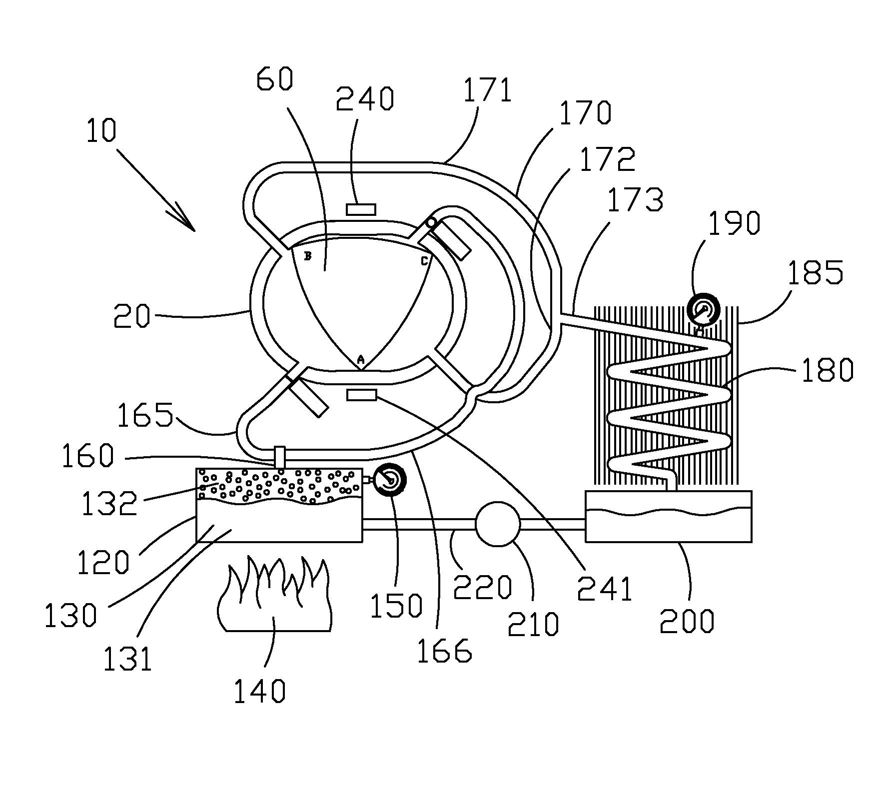
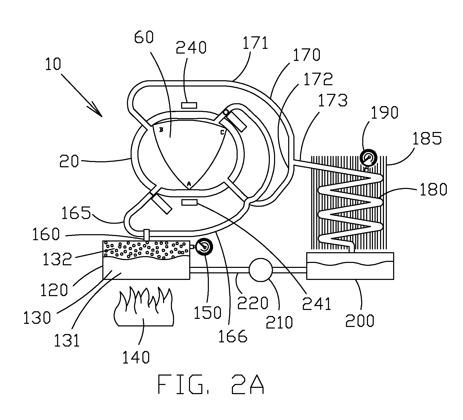
[0085]Looking now to FIG. 2A, it is seen that an engine 10 is provided having a housing 20. A rotor 60 is further provided. The rotor 60 rotates within the housing 20 as described below.

[0086]A high pressure tank 120 is provided. The tank can be any suitable size. The tank 120 can hold a selected amount of working medium 130. The working medium is preferably a commonly available refrigerant that undergoes a phase change between liquid 131 and gas 132 at predictable temperatures and pressures. One preferred refrigerant is R-123. However it is understood that other refrigerants could be used without departing from t...


PUM


Abstract

The present invention relates to a heat engine having a housing. A generally triangular shaped rotor can drive an offset crank as it eccentrically rotates within the housing. Two inlets with valves and two exhausts are provided. The volume between each face of the rotor and the housing defines three expansion chambers. Six power cycles are provided (one by each expansion chamber times two inlets) per revolution of the rotor. Each valve controls the length of time that high pressure gas is allowed to enter each expansion chamber. The valves are controlled by a processor and close when enough pressure is supplied so that the pressures inside and outside the expansion chamber are equal when the chamber is fully expanded just prior to exhaust. Gates can provide a mechanical advantage to the rotor by reducing the amount of pressure applied to the back side of the fulcrum.

Description

[0001]This patent application claims priority on and the benefit of U.S. provisional application 61 / 485,849 filed May 13, 2011, the entire contents of which are hereby incorporated herein by reference.BACKGROUND OF THE INVENTION[0002]1. Field of the Invention[0003]The present invention relates to a heat engine, and in particular to a rotary style heat engine operating with increased efficiency.[0004]2. Description of the Related Art[0005]Heat energy, sometimes called thermal energy, is defines as the kinetic energy of a system's particles. Put another way, the heat energy of a system is the amount of potential energy in a system that is derived from the heat content within the system.[0006]Temperature is not the same as heat energy. Yet, temperature makes up an integral part of the ideal gas law. The ideal gas law states:PV=nRT[0007]Wherein:[0008]P is Pressure[0009]V is Volume[0010]n is the amount of gas[0011]R is the universal gas constant and[0012]T is temperature[0013]This ideal ...

Claims


Application Information

Patent Timeline
Patent Type & Authority Patents(United States)
IPC IPC(8): F02B53/12F01C1/22F01C19/02F01C21/18
CPCF01C1/22F01C21/18F01C19/02
Inventor DAVIS, BRIAN
Owner DAVIS BRIAN
Why Eureka
Try Eureka