Piezoelectric pump

A piezoelectric pump and piezoelectric vibrator technology, which can be used in pumps, pumps with flexible working elements, and liquid variable-capacity machines, etc., can solve the problems of complex valve assembly, high assembly precision requirements, and inconvenience in mass production.

Inactive Publication Date: 2016-03-02
刘平
View PDF0 Cites 0 Cited by
  • Summary
  • Abstract
  • Description
  • Claims
  • Application Information

AI Technical Summary

Problems solved by technology

[0003] In order to solve the inconvenience of large-scale production caused by the complex valve assembly and high assembly precision requirements in the process of miniaturization of piezoelectric pumps, a piezoelectric pump is proposed, which consists of two parts, namely, a piezoelectric vibrator and

Method used


Image

  • Piezoelectric pump
  • Piezoelectric pump
  • Piezoelectric pump

Examples


Embodiment Construction

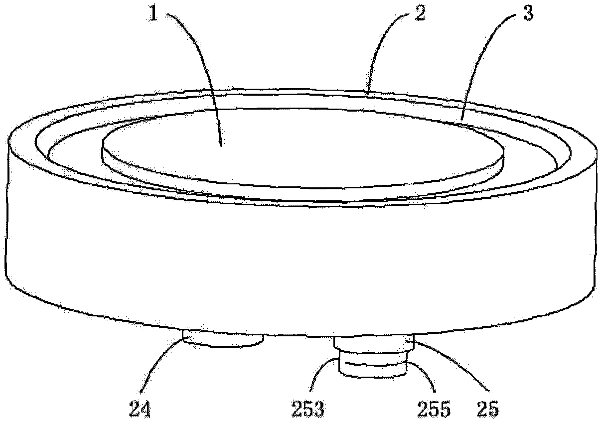
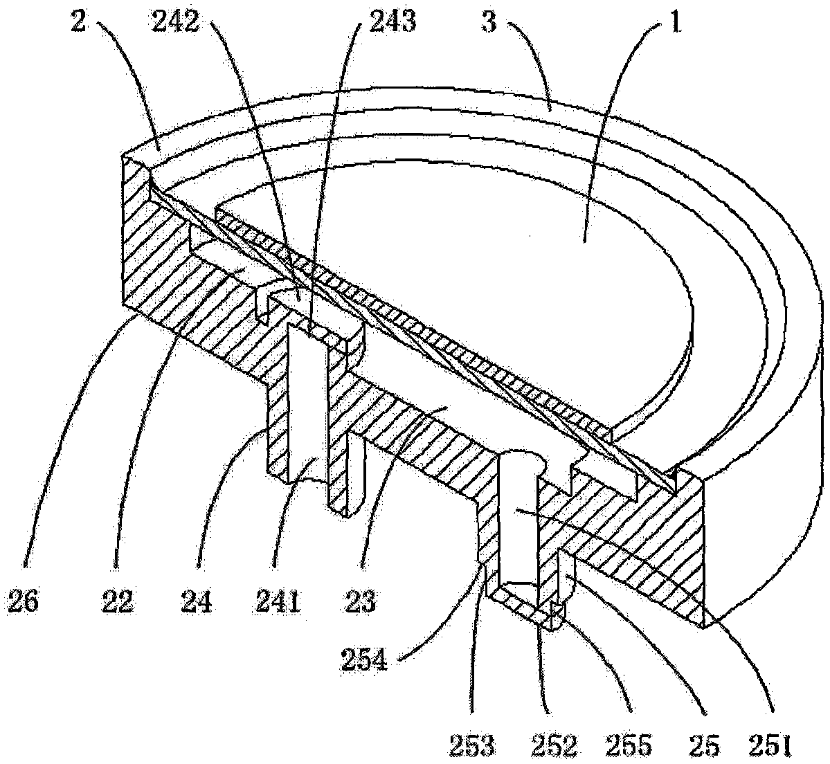
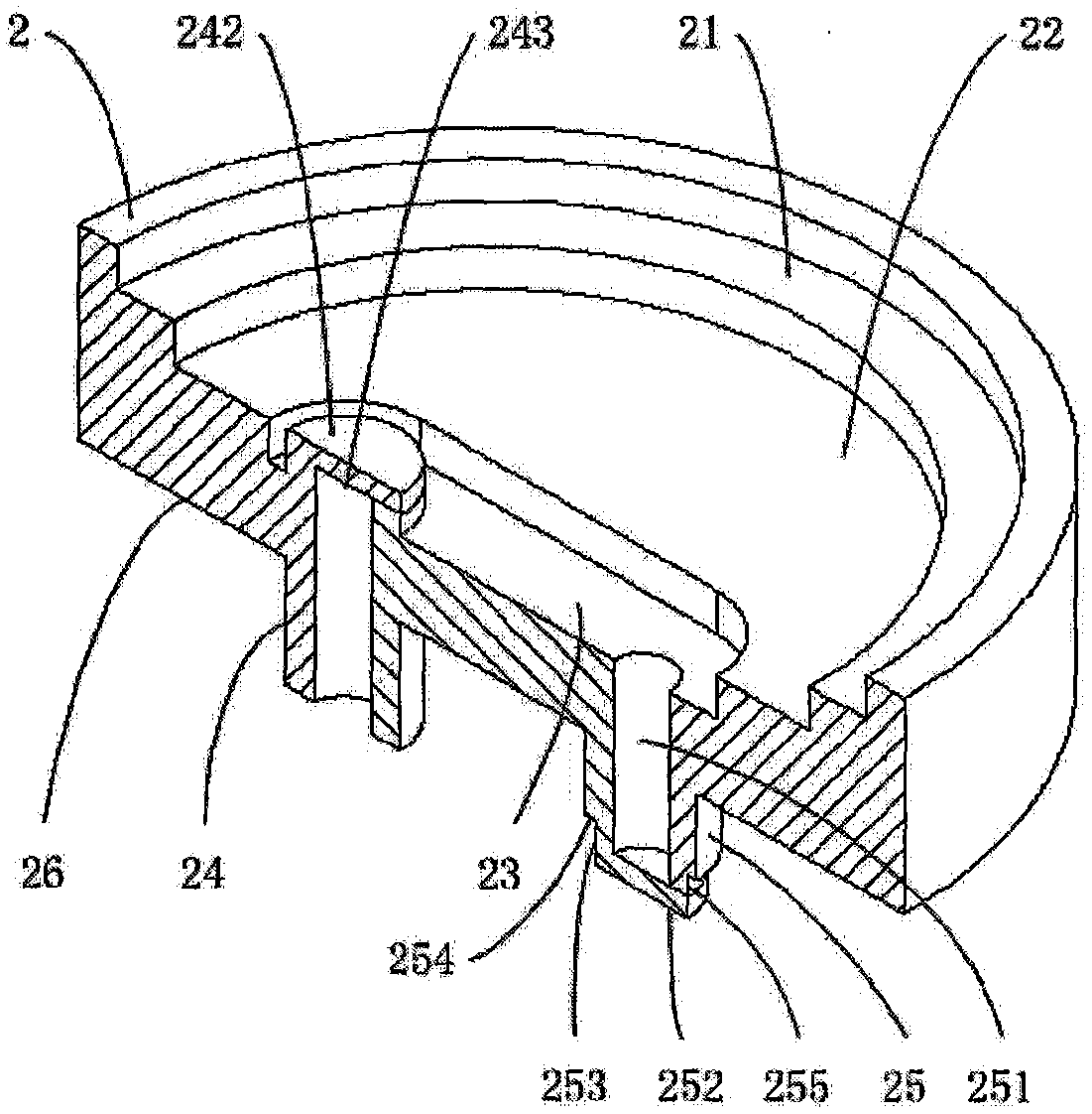
[0012] refer to figure 1 , the piezoelectric pump of the present invention is composed of a piezoelectric vibrator 1 and an integral cavity valve part 2, wherein:

[0013] The piezoelectric vibrator 1 is installed on one side of the integrated cavity valve part 2; the integrated cavity valve part 2 is made of a rubber material or rubber and plastic materials, and the vibrator installation groove is arranged on the integrated cavity valve part 21. The piezoelectric vibrator 1 is installed in the vibrator installation groove 21, and a cavity sinker 22 is arranged in the center of the vibrator installation groove 21. After the piezoelectric vibrator 1 is installed, the cavity sinker 22 forms a sealed cavity, that is, a pump cavity. A diversion groove 23 is arranged at the bottom of the cavity sinker 22, and the inlet 24 and outlet 25 of the cavity are arranged at the bottom of the diversion groove 23; the inlet 24 is a cylindrical structure with an inlet sink hole 241 inside, arr...


PUM


Abstract

The invention relates to a piezoelectric pump. A piezoelectric vibrator is used as a driving element; the piezoelectric pump comprises an integrated cavity valve part; the piezoelectric vibrator is arranged at one side of the integrated cavity valve part; a cavity sunken groove is formed in a position, corresponding to the piezoelectric vibrator, on the integrated cavity valve part; after being mounted, the piezoelectric vibrator forms a sealing cavity, namely a pump cavity together with the cavity sunken groove; a diversion trench is arranged at the bottom of the cavity sunken groove; a cavity inlet and a cavity outlet are formed in the bottom of the diversion trench; the piezoelectric vibrator generates forward and backward bending deformation under the action of an alternating voltage to enable the volume of a cavity to be changed; when the volume of the pump cavity is increased, the pressure is reduced, an opening of an inlet valve is opened, an opening of an outlet valve is closed, and a fluid flows from the inlet to the cavity; and when the volume of the pump cavity is reduced, the pressure is increased, the opening of the inlet valve is closed, and the opening of the outlet valve is opened, and the fluid flows out from the outlet to form pumping capacity. The piezoelectric pump has the advantage of simplicity in assembly.

Description

technical field [0001] The invention belongs to the field of fluid delivery, and in particular relates to a piezoelectric pump device. Background technique [0002] Piezoelectric pump is a micro-sized volumetric pump driven by piezoelectric vibrators. It has the advantages of simple structure for mass production, small size for miniaturization, digital control and long life. It is widely used in instrumentation, testing equipment and mechanical electronics. It has broad application prospects. Existing piezoelectric pumps include several typical forms of sheet bending direct drive, stack push diaphragm drive and resonance amplification drive. The above types of pumps include valve pumps and valveless pumps according to the types of valves. The output performance of the pump is obviously stronger than that of the valveless pump. Due to the small change in the cavity volume of the piezoelectric pump, the cut-off requirements for the check valve are higher than those of the tr...

Claims


Application Information

Patent Timeline
IPC IPC(8): F04B43/04
CPCF04B43/046
Inventor 刘平
Owner 刘平
Why Eureka
Try Eureka