Eureka AIR delivers breakthrough ideas for toughest innovation challenges, trusted by R&D personnel around the world.

Steel-aluminum guide rail

A guide rail, steel and aluminum technology, applied in the field of guide rails, can solve the problems of poor load-bearing capacity and high cost of guide rails, and achieve the effect of improving load-bearing capacity and service life, low cost, and improving guide rail load-bearing capacity.

Inactive Publication Date: 2016-03-02
周朝强
View PDF5 Cites 2 Cited by
  • Summary
  • Abstract
  • Description
  • Claims
  • Application Information

AI Technical Summary

Problems solved by technology

[0003] The invention provides a new steel-aluminum guide rail aiming at the defects of poor load-bearing capacity of the guide rail and high cost when raising the load-bearing capacity in the prior art.

Method used


Image

  • Steel-aluminum guide rail
  • Steel-aluminum guide rail
  • Steel-aluminum guide rail

Examples


Embodiment 1

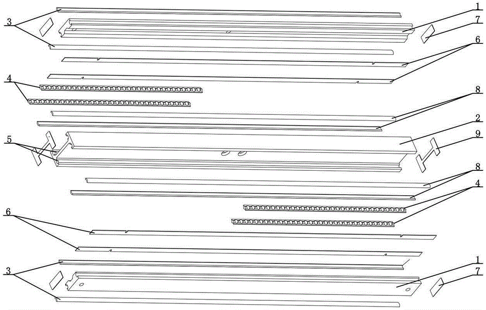
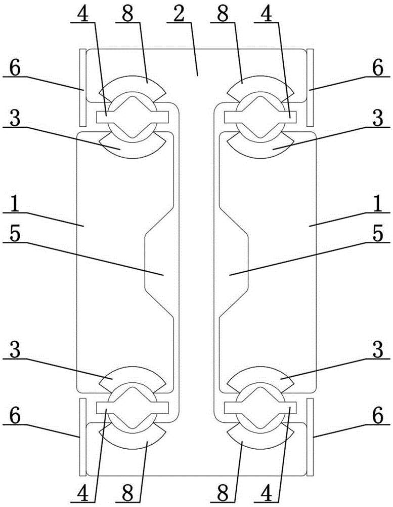
[0022] like figure 1 , figure 2 , image 3 As shown, a steel-aluminum guide rail includes movable load-bearing rails 2, two sets of slide rails 1, and sliding auxiliary parts 4. Grooves 5 are respectively arranged on both sides of the movable load-bearing rails 2, and the two sets of slide rails 1 The sliding auxiliary parts 4 are slidably arranged in the grooves 5 on both sides of the movable load-bearing rail 2 respectively. A first wear-resistant part 3 is arranged between the sliding auxiliary parts 4 and the slide rail 1. The sliding auxiliary parts 4 A second wear-resistant part 8 is arranged between the movable load-bearing rail 2, and the material of the movable load-bearing rail 2 and the slide rail 1 is aluminum alloy, and the first wear-resistant part 3 and the second wear-resistant part 8 are The materials are all steel, and the first wear-resistant part 3 and the second wear-resistant part 8 are strip-shaped and embedded in the slide rail 1 and the movable load...

Embodiment 2

[0031] like Figure 4 , Figure 5 , Figure 6 As shown, a steel-aluminum guide rail includes movable load-bearing rails 2, two sets of slide rails 1, and sliding auxiliary parts 4. Grooves 5 are respectively arranged on both sides of the movable load-bearing rails 2, and the two sets of slide rails 1 The sliding auxiliary parts 4 are slidably arranged in the grooves 5 on both sides of the movable load-bearing rail 2 respectively. A first wear-resistant part 3 is arranged between the sliding auxiliary parts 4 and the slide rail 1. The sliding auxiliary parts 4 A second wear-resistant part 8 is arranged between the movable load-bearing rail 2, and the material of the movable load-bearing rail 2 and the slide rail 1 is aluminum alloy, and the first wear-resistant part 3 and the second wear-resistant part 8 are The material is all steel, the first wear-resistant part 3 and the second wear-resistant part 8 are in the shape of slide rails, and the second wear-resistant part 8 is i...


PUM

PropertyMeasurementUnit
Tensile lengthaaaaaaaaaa

Abstract

The invention discloses a steel-aluminum guide rail which comprises a movable bearing rail, two groups of slide rails and sliding auxiliary parts, wherein grooves are formed in the two sides of the movable bearing rail respectively; the two groups of slide rails are arranged in the grooves formed in the two sides of the movable bearing rail in a sliding mode through the sliding auxiliary parts respectively; a first wear resistant part is arranged between each sliding auxiliary part and each group of slide rails; a second wear resistant part is arranged between each sliding auxiliary part and the movable bearing rail; the movable bearing rail and the slide rails are all made of aluminum alloy; and the first wear resistant parts and the second wear resistant parts are all made of steel. The steel-aluminum guide rail can greatly promote the bearing capability of the guide rail and prolong the service life, has very excellent performance and is lower in cost compared with the traditional guide rail with the same bearing capability.

Description

technical field [0001] The invention relates to a guide rail, in particular to a steel-aluminum guide rail. Background technique [0002] A guide rail is a workpiece that enables objects to carry reciprocating telescopic movements on the guide rail. The existing industrial guide rails are generally three-section guide rails, including inner rails, middle rails and outer rails. And the compression caused by the inner rail makes the deformation of the three-section guide rail more serious after being fully stretched. In addition, the current guide rail is generally made of steel, because steel has high density, high hardness, and good tensile resistance, which can well meet industrial requirements. But on the other hand, due to the heavy weight of the steel itself, the overall weight of the steel guide rail is heavier, which further aggravates the deformation of the guide rail after it is fully stretched, so that the steel guide rail with a fully stretched length of 1200mm ca...

Claims


Application Information

Patent Timeline
IPC IPC(8): F16C29/00F16C29/04F16C29/08
CPCF16C29/082F16C29/005F16C29/046F16C29/048F16C33/62F16C29/004F16C29/043F16C29/086
Inventor 周朝强
Owner 周朝强
Why Eureka
Eureka Blog
Learn More