
Electrical drive valve

An electric drive, stopper technology, applied in the direction of lift valve, valve device, engine components, etc., can solve the problems of wear of sliding parts, high touch energy, wear, etc., to improve durability and reliability, and improve wear resistance. damage, and the effect of preventing malfunction

Active Publication Date: 2016-03-02
FUJIKOKI MFG CO LTD
View PDF10 Cites 4 Cited by
  • Summary
  • Abstract
  • Description
  • Claims
  • Application Information

AI Technical Summary

Problems solved by technology

[0014] That is, in the conventional electric valve of the first form, when the movable stopper touches the fixed stopper and the rotation and descent of the valve shaft holder is forcibly stopped, the coil spring is compressed to obtain the resulting cushioning. effect, but in the electric valve of the third form, since the valve core does not sit on the valve seat, the coil spring installed between the valve shaft holder and the valve shaft will not be further compressed, and the above-mentioned effect cannot be obtained. Cushioning effect, the contact energy of the movable stopper against the fixed stopper is greater than that of the former, and sometimes the two stoppers made of resin will be worn
[0015] If the stopper is worn, the contact position between the movable stopper and the fixed stopper will deviate, and the base point will deviate, etc., and the flow adjustment of the small opening cannot be performed correctly. In addition, not only the electric valve, In equipment including compressors installed in the refrigerant circuit, the sliding parts may be worn or clogged due to abrasive powder, and malfunctions or malfunctions such as locking of constituent parts may easily occur.

Method used


Image

  • Electrical drive valve
  • Electrical drive valve

Examples


Embodiment Construction

[0056] Embodiments of the present invention will be described below with reference to the accompanying drawings.

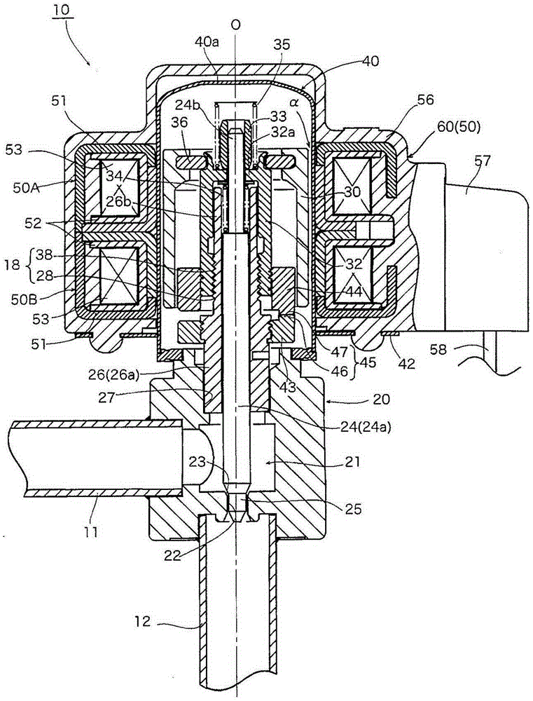
[0057] figure 1 An example of an electric valve as an electrically driven valve of the present invention is shown.

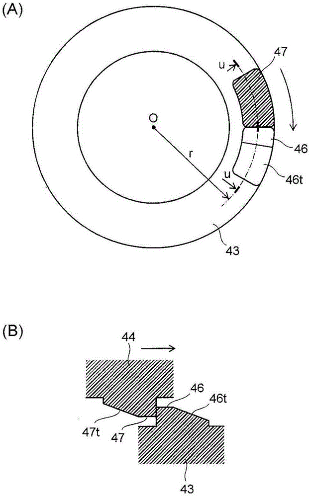
[0058] The electric valve 10 of the illustrated example has: a screw feed mechanism 18, which is used to utilize the rotation of the rotor 30 to make the valve core 25 contact and separate from the valve seat 23; The stopper 47 and the stopper mechanism 45 constituted by the fixed stopper 46 disposed on the valve seat 23 side (valve main body 20 side), before the valve core 25 is seated on the valve seat 23, the slightly opened micro-opening degree In the state, the movable stopper 47 is brought into contact with the fixed stopper 46 so as not to be in the closed state.

[0059] In detail, the electric valve 10 has: a valve shaft 24, the lower end of which is integrally provided with a valve core 25 having an inverted truncated cone; a valve main ...


PUM


Abstract

A electrical drive valve used as a material for specific parts such as retainers (46, 47) is directly exposed in a coolant and is repetitively touched and impacted. The valve uses the following materials: PPS resin with high hardness and excellent chemical resistance, any one of PEEK resin and PTFE resin as a parent material, and reinforcement material with lower hardness than the parent material and with solid lubricant property, such as carbon, graphite, carbon fibers and other carbon substances, the reinforcement materials being mixed into the parent material. The valve can improve the wear resistance of parts subjected to repeated hitting and impact such as retainers, bad actions induced by abrasion powder are not likely to be generated, and the endurance and reliability can be improved.

Description

technical field [0001] The invention relates to an electrically driven valve such as an electric valve and a solenoid valve, in particular to an electrically driven valve suitable for use in a refrigeration cycle of a refrigerant cycle. Background technique [0002] As one of the electrically driven valves used in the refrigeration cycle of the refrigerant cycle, there are, for example, electric valves described in Patent Documents 1 and 2, which have a screw feed mechanism that utilizes the movement of the rotor. Rotate to make the valve core come into contact with and separate from the valve seat; and a stopper mechanism (movable stopper, fixed stopper) made of synthetic resin that determines the movable range of the valve core. [0003] In the electric valve of the first form, a screw feed mechanism is constituted, which includes: a fixed thread portion (external thread portion) formed on the outer periphery of a guide sleeve fixed to the valve main body; a moving thread ...

Claims


Application Information

Patent Timeline
IPC IPC(8): F16K1/32
CPCF16K1/32
Inventor 菅沼威菱谷康平猪野泰利
Owner FUJIKOKI MFG CO LTD
Learn More