
Mixed type fiber-optic gyroscope signal filtering method based on EEMD and FIR

A fiber optic gyroscope and signal filtering technology, applied in Sagnac effect gyroscopes and other directions, can solve problems such as zero bias instability, and achieve the effect of enhancing filtering effect, improving data decomposition accuracy, and wide application.

Active Publication Date: 2016-03-02
HARBIN INST OF TECH
View PDF5 Cites 5 Cited by
  • Summary
  • Abstract
  • Description
  • Claims
  • Application Information

AI Technical Summary

Problems solved by technology

[0052] (4) Bias instability

Method used


Image

  • Mixed type fiber-optic gyroscope signal filtering method based on EEMD and FIR
  • Mixed type fiber-optic gyroscope signal filtering method based on EEMD and FIR
  • Mixed type fiber-optic gyroscope signal filtering method based on EEMD and FIR

Examples


specific Embodiment approach 1

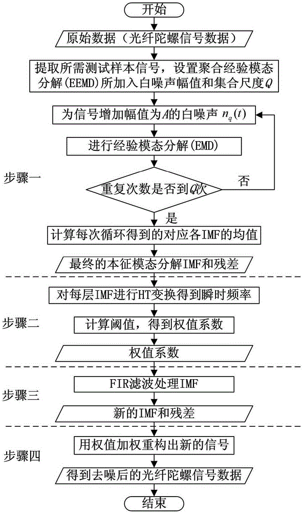
[0107] Specific embodiment one: a kind of hybrid fiber optic gyroscope signal filtering method based on EEMD and FIR, such as figure 1 As shown, it is divided into four steps, and the specific steps are as follows:

[0108] Step 1: Use the EEMD algorithm to decompose the FOG signal.

[0109] Perform EEMD decomposition on the fiber optic gyroscope signal x(t) to obtain k IMF components.

[0110] ① Add white noise n with amplitude A to the input signal x(t) q (t), thus forming a new signal x q (t):

[0111] x q (t)=x(t)+An q (t).

[0112] The upper limit of the selection of the amplitude A is generally 0.2 times the maximum amplitude of the input signal, and the selection range is 0.1 times to 0.5 times the standard deviation of the signal.

[0113] ② Carry out EMD decomposition on the newly generated signal to obtain the intrinsic mode function IMF set of this experiment.

[0114] The screening and decomposition process of EMD is summarized as follows:

[0115] (1) Get s...

specific Embodiment approach 2

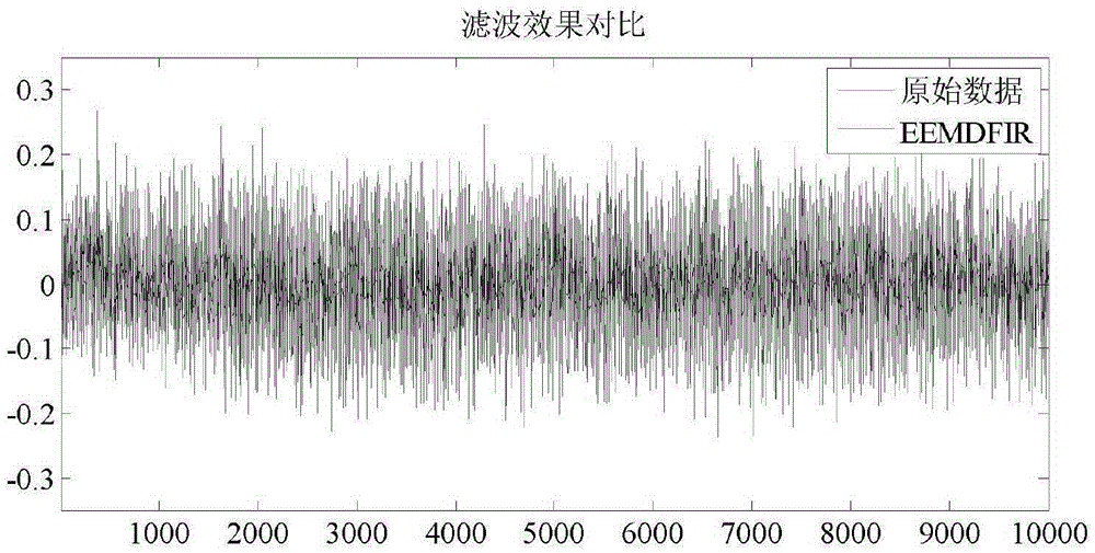
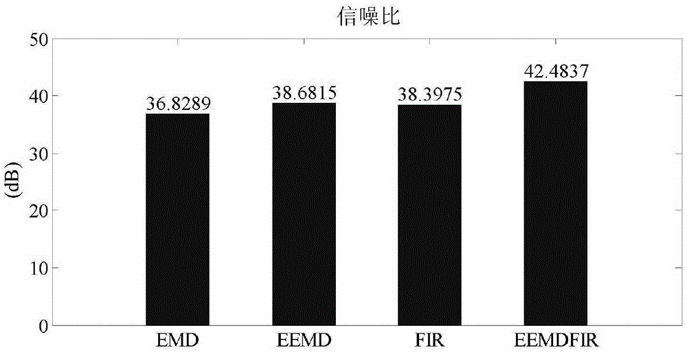
[0155] Specific Embodiment 2: In this embodiment, a group of signal data output by a real fiber optic gyroscope is selected to verify the present invention, so that the method of the present invention is used to perform filtering processing on the fiber optic gyroscope data.

[0156] First select the gyroscope data. The test equipment of the present invention mainly includes a high-precision single-axis rate turntable and a dsPIC single-chip microcomputer acquisition processor. The test sensor is the XW-GS1810-100 fiber optic gyroscope. XW-GS1810-100 fiber optic gyroscope is an all-solid-state medium-precision inertial sensor device independently developed by Beijing Xingwang Yuda Technology Development Co., Ltd., which integrates light, mechanics and electricity. It has the characteristics of high reliability, wide response frequency, simple power supply, and low power. It is mainly suitable for control applications such as stable platforms and dynamic image stabilization. I...


PUM


Abstract

The invention discloses a mixed type fiber-optic gyroscope signal filtering method based on EEMD and FIR. The method specifically comprises the following steps that 1, a fiber-optic gyroscope signal is decomposed through an EEMD algorithm to obtain IMF components and residual errors of all layers; 2, Hilbert transform is performed on the IMF components of all the layers to obtain amplitude values and instantaneous frequencies of all the layers, threshold values are reckoned according to the instantaneous frequencies, and weight values are calculated through the threshold values; 3, FIR filtering processing is performed on the IMF components and the residual errors of all the layers by adopting an FIR filter, and then new IMF components and new residual errors of all the layers are obtained; 4, weighting reconstruction is performed on the new IMF processed by the FIR filter, and finally a denoised result is formed. According to the mixed type fiber-optic gyroscope signal filtering method based on the EEMD and the FIR, the advantages of the two methods are integrated, the data decomposition precision is improved through the EEMD method, low-pass filtering is further performed through the FIR filter method, therefore, the frequency precision during EEMD signal processing is improved, and the filtering effect is significantly enhanced; meanwhile, it is guaranteed that the method is still based on data, modeling does not need to be performed on the data, and the application range is wide.

Description

technical field [0001] The invention belongs to the field of fiber optic gyroscope signal processing, and relates to a fiber optic gyroscope signal filtering method based on empirical mode processing and a finite-length impulse response filter based on hybrid processing. Background technique [0002] The gyroscope is an instrument based on the Sagnac effect, and its main characteristics are stability and precession. Good performance makes it widely used in aviation, aerospace and navigation fields. Gyroscopes are generally divided into piezoelectric gyroscopes, electromechanical gyroscopes, laser gyroscopes, and fiber optic gyroscopes. [0003] Compared with other types of gyroscopes, fiber optic gyroscopes have the advantages of small size, light weight, and low cost, making them popular and widely used. However, because the fiber optic gyroscope contains photosensitive elements inside, it is easily affected by various factors such as internal structure and temperature dr...

Claims


Application Information

Patent Timeline
Patent Type & Authority Applications(China)
IPC IPC(8): G01C19/72
CPCG01C19/72
Inventor 张淼沈毅郑菱莎王天成张晔
Owner HARBIN INST OF TECH
Learn More