Supercharge Your Innovation With Domain-Expert AI Agents!

Waterproof wire arranging female groove

A waterproof, busway technology, applied in the direction of fully enclosed busbar devices, can solve the problems of irregular installation process, influence of busbar operation, electrical accidents, etc., and achieve the effect of high reliability, good stability and easy operation.

Inactive Publication Date: 2016-03-02
重庆吉能变压器有限公司
View PDF0 Cites 0 Cited by
  • Summary
  • Abstract
  • Description
  • Claims
  • Application Information

AI Technical Summary

Problems solved by technology

The busway with this structure has the following problems during use: the busway is used as a power distribution device for transmitting current. According to different installation environments, the busway is sometimes exposed in the air. The cover plate will flow down along the edge of the cover plate. Since the two ends of the housing are connected to the transformer terminals and electrical equipment, the rainwater flowing down the ends of the cover plate will flow into the terminals of the transformer or the electrical equipment, causing electrical shock. Accident, there is a great safety hazard
In the actual use process, due to the long distance of the current transmission, it is usually necessary to connect multiple shells in series, and the adjacent shells are connected by bolts. During use, it is found that due to the manufacturing process of the shell, Irregular installation process and design defects, etc. After connecting multiple shells into one body, there are gaps in the connection parts of adjacent shells. In rainy days, rainwater will flow into the bus duct along the gap, causing damage to the operation of the bus duct. Affected, thus causing electrical accidents, there is a great potential safety hazard, so a waterproof type busbar is needed to solve the above problems

Method used


Image

  • Waterproof wire arranging female groove
  • Waterproof wire arranging female groove

Examples


Embodiment Construction

[0013] In order to make the technical means, creative features, goals and effects achieved by the present invention easy to understand, the present invention will be further described below in conjunction with specific embodiments.

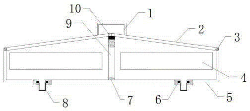
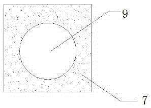
[0014] see figure 1 and figure 2 , the present invention provides a technical solution: a waterproof type cable busbar, including a handle 1, an end cover 2, a rotating shaft 3, a busbar 4, a mounting groove 5, a fixing chute 6, a connecting plate 7, a water tank 8, a through The hole 9 and the magnet 10, the installation groove 5 is arranged parallel to the horizontal plane and the upper end surface of the installation groove 5 is removed, the bus bar 4, the connection plate 7, the water tank 8, the through hole 9 and the magnet 10 are located inside the installation groove 5, and the connection plate 7 is Rectangular plate structure, the connecting plate 7 is located in the middle of the installation groove 5, the through hole 9 is located on ...


PUM


Abstract

The invention provides a waterproof wire arranging female groove. An installation groove is arranged in parallel to a horizontal plane, an upper end surface of the installation groove is removed, a connection plate is of a rectangular plate-shaped structure and is arranged at the middle position of the interior of the installation groove, a penetrating hole is arranged on the connection plate and particularly arranged at the middle position of the connection plate, a magnet is fixedly arranged at the upper end of the connection plate and is of an elongate structure, buses are arranged in the installation groove and particularly arranged at the two ends of the connection plate, two end covers are arranged at the upper end of the installation groove, the installation groove and the end covers are connected via rotary shafts, and a handle is arranged at the upper ends of the end covers. The rotation of the end covers is achieved by additionally arranging the handle; with the design of a shading plate at the upper end of the handle, rainwater can be effectively prevented from entering the installation groove; and with the design of fixed sliding grooves and water receiving drums, logged water in the installation groove can be conveniently cleaned and is further prevented from flowing out of the installation groove to damage other electric devices.

Description

technical field [0001] The invention is a waterproof type busbar, which belongs to the field of electrical equipment. Background technique [0002] In the prior art, with the emergence of modern engineering facilities and equipment, the power consumption of all walks of life increases rapidly, especially high-rise buildings and large workshops require huge power. In order to adapt to the increasingly taller buildings and To meet the needs of economical and reasonable wiring in large-scale factories, bus ducts are usually used as power distribution devices for transmitting current. At present, the bus ducts used include a shell composed of a bottom plate, a side plate, and a cover plate, and a bus bar is arranged inside the shell. Both ends of the housing are provided with insulating plates, and the side plates are provided with ventilation fins. When the busway is in use, only one end of the busbar needs to be connected to the transformer terminal or other power supply equip...

Claims


Application Information

Patent Timeline
IPC IPC(8): H02G5/06
CPCH02G5/06
Inventor 张勇周安根
Owner 重庆吉能变压器有限公司
Features
  • R&D
  • Intellectual Property
  • Life Sciences
  • Materials
  • Tech Scout
  • Unparalleled Data Quality
  • Higher Quality Content
  • 60% Fewer Hallucinations
Learn More