
City center area power distribution network and load transfer method

A load transfer, central area technology, applied in electrical components, circuit devices, AC network circuits, etc., can solve problems such as poor line transfer capacity, chaotic layout of busbar points in current stations, and sharp increase in the workload of transfer plan analysis. , to achieve the effect of improving efficiency

Inactive Publication Date: 2016-03-02
SHANGHAI MUNICIPAL ELECTRIC POWER CO +1
View PDF2 Cites 12 Cited by
  • Summary
  • Abstract
  • Description
  • Claims
  • Application Information

AI Technical Summary

Problems solved by technology

[0002] With the improvement of people's quality of life, some new problems are gradually exposed in the traditional distribution network planning: the busbar of the substation in the urban center tends to be saturated; the load level of equipment is high; Pipeline congestion; development of distribution automation lags behind, etc.
[0010] However, since the urban distribution network structure is more complex than that in general areas, in order to meet the power supply capacity and reliability requirements of important users, the connections between different power sources have increased.
With the increase of contact lines, the time for regulators and transporters to analyze and formulate the transfer plan will increase accordingly, and the power outage time will inevitably be extended in the case of accident handling; the increase in transfer routes will cause a sharp increase in the workload of transfer plan analysis, which will easily lead to regulation. Errors in formulating plans for personnel and transport personnel and errors in calculation of load ratios increase the risk to the normal operation of the system

Method used


Image

  • City center area power distribution network and load transfer method
  • City center area power distribution network and load transfer method

Examples


Embodiment Construction

[0041] Specific embodiments of the present invention will be further described below in conjunction with the accompanying drawings.

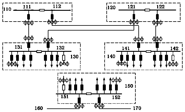
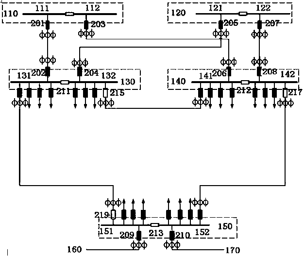
[0042] based on figure 1 A distribution network in a city center area is shown in , and this embodiment discloses a wiring scheme for load transfer of a city center area distribution network.

[0043] like figure 2 and combine figure 1As shown, the distribution network in the central city area in this embodiment includes: the first substation bus 110, the first switchyard bus 131 connected to the first substation bus 110, the second substation bus 120, and the second substation bus 120 circuit The connected second switchyard bus 140 , the third substation bus 150 , the fourth substation bus 160 , the third switchyard bus 150 in circuit connection with the third 160 and fourth 170 substation buses. The first substation bus 110, the first switching station bus 130, the second substation bus 120, the second switching station bus 140, the third ...


PUM


Abstract

The invention discloses a city center area power distribution network. Buses of a first switch station bus, a second switch station bus and a third switch station bus are respectively preset with a private line connection position, every two of the private line connection positions of the first switch station bus, the second switch station bus and the third switch station bus are in circuit connection through connection wires, and a first transformer station bus, a second transformer station bus, a third transformer station bus and a fourth transformer station bus form two main configurations and two standby configurations. The power distribution network employs grid design thinking, a corresponding target wiring load transfer strategy analysis model is established, power supply capacity and reliability requirements of important users are satisfied, and transfer scheme making efficiency of regulators and operators is improved.

Description

technical field [0001] The invention relates to an urban power distribution technology, in particular to a distribution network in a city center area and a load transfer method. Background technique [0002] With the improvement of people's quality of life, some new problems are gradually exposed in the traditional distribution network planning: the busbar of the substation in the urban center tends to be saturated; the load level of equipment is high; Pipeline congestion; lagging development of distribution automation, etc. [0003] Based on the above problems, the grid planning concept of distribution network is proposed. That is to manage the distribution network with the grid as the unit, including the planning, construction, operation and maintenance of the distribution network. This management method can provide decision-making basis and reference for distribution network expansion, project reserve, reliability management, line loss management, basic ledger managemen...

Claims


Application Information

Patent Timeline
IPC IPC(8): H02J3/00
CPCH02J3/0073
Inventor 王赛一贾建军沈建许浩钧吴正骅徐文进闾文浩华月申陈东张麟盛佳蓉谢旗辉李红英侯四维
Owner SHANGHAI MUNICIPAL ELECTRIC POWER CO
Learn More