
A driving power circuit for an electric dehumidifier

A technology for driving power supply and dehumidifier, which is applied to emergency protection circuit devices, electrical components, output power conversion devices, etc. Constant current function and other issues, to protect the life of important components and power supplies, avoid contact aging, increase the number of switches and service life

Inactive Publication Date: 2018-03-02
宋业贵
View PDF5 Cites 0 Cited by
  • Summary
  • Abstract
  • Description
  • Claims
  • Application Information

AI Technical Summary

Problems solved by technology

Its circuit can only achieve constant voltage function, but not constant current function, resulting in low dehumidification efficiency of the dehumidifier, which in turn affects the service life of the entire dehumidifier
Therefore, it cannot meet the current-carrying value and non-overflow characteristics of the dehumidifier, and needs to be improved.

Method used


Image

  • A driving power circuit for an electric dehumidifier
  • A driving power circuit for an electric dehumidifier
  • A driving power circuit for an electric dehumidifier

Examples


Embodiment Construction

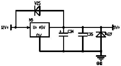
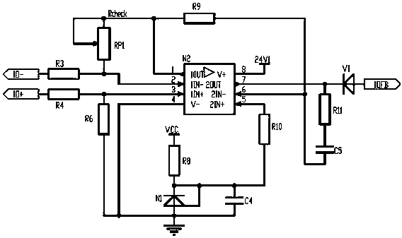
[0031] The drive power supply circuit of the electric dehumidifier in the present invention includes a main chip, a control board, and a power supply circuit for the control board. Circuit connection; through the control board to control the working status of the fan and cooling plate, and timely find out the failure of external devices such as the fan and cooling plate.

[0032] The control circuit includes an EMI filter circuit. The EMI filter circuit filters the input AC power and converts it into DC power through the power frequency rectification unit, and then converts the DC power into high-frequency pulse voltage through the main chip, and at the same time converts the electric energy into The magnetic energy is transmitted to the secondary side of the transformer; the magnetic energy of the secondary side of the transformer is converted into direct current by the high-frequency rectification part and divided into three main circuits of the secondary side, of which the m...


PUM


Abstract

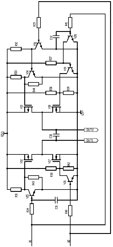
The invention provides a driving power supply circuit for an electric dehumidifier. The driving power supply circuit comprises a main chip, a control board and a control board power supply circuit; the control board is connected with an H bridge, the control board power supply circuit, a fault warning circuit and a control circuit separately through a 16-core flat cable; the control circuit comprises an EMI filter circuit; the input alternating current power supply is filtered by the EMI filter circuit, and converted into direct current through a power frequency rectifying part, and then the direct current is converted into high frequency pulse voltage through the main chip; meanwhile, the electric energy is converted into magnetic energy through a transformer, and the magnetic energy is transmitted to the secondary side of the transformer; the magnetic energy in the secondary side of the transformer is converted into direct current through a high frequency rectifying part, and the direct current is connected with a fan, the H bridge, the main chip and the control board power supply circuit separately; and the H bridge outputs the power supply with variable a positive electrode and a negative electrode by changing the magnitude of electrical levels, and controls the output and the disconnection of the power supply, and the power supply supplies power to enable a load refrigeration piece to work. The constant current circuit has the characteristics of constant current and constant voltage, and has the functions of input overload protection, overvoltage protection, lightning stroke protection and surge protection, as well as the over-temperature protection in work.

Description

technical field [0001] The invention relates to a power supply circuit, in particular to a drive power supply circuit for an electric dehumidifier. Background technique [0002] Dehumidifiers, also known as dehumidifiers, dryers, or dehumidifiers, remove moisture from the air. A dehumidifier is an air conditioner that puts the heating and cooling coils in the same box, that is, a fan pumps the indoor air to the cooling coil of the air conditioner to condense the moisture, and then the dry air passes through the heating coil and is heated to the original temperature. A conventional dehumidifier consists of a compressor, a heat exchanger, a fan, a water container, a casing and a controller. Its working principle is: the humid air is sucked into the machine by the fan, and passes through the heat exchanger. At this time, the water molecules in the air are condensed into water droplets, and the dry air after treatment is discharged outside the machine. This cycle keeps the indo...

Claims


Application Information

Patent Timeline
Patent Type & Authority Patents(China)
IPC IPC(8): H02M1/10H02H7/125
CPCH02H7/125H02M1/10
Inventor 宋业贵
Owner 宋业贵
Learn More