Pressure induced gas generator system for electrolysis

A gas generator and main body technology, applied in electrical control, electrolysis components, electrolysis process, etc., can solve problems such as expensive and redesigned exhaust systems

Inactive Publication Date: 2016-03-02
CFT GLOBAL
View PDF5 Cites 1 Cited by
  • Summary
  • Abstract
  • Description
  • Claims
  • Application Information

AI Technical Summary

Problems solved by technology

These references disclose complex and expensive equipment and methods for producing hydrogen using electrolyzers and may even require extensive redesign of standard diesel engines and engine exhaust systems

Method used


Image

  • Pressure induced gas generator system for electrolysis
  • Pressure induced gas generator system for electrolysis
  • Pressure induced gas generator system for electrolysis

Examples


Embodiment Construction

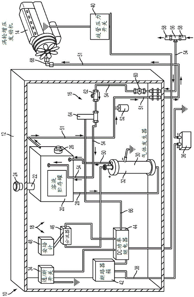
[0024] figure 1 is a schematic illustration of a pressurized electrolysis system according to embodiments discussed herein. The pressurized electrolysis system is generally identified by reference numeral 10 . Pressurized electrolysis system 10 is mountable in system housing 12 and is adapted to introduce a pressurized gas mixture to an engine. exist figure 1 In, by way of example and not limitation, a pressurized electrolysis system 10 is shown introducing a pressurized gas mixture into the intake manifold of a turbocharged diesel engine 14 . The pressurized electrolysis system 10 according to the present disclosure may also be used with other types of engines, such as gasoline engines, diesel engines, natural gas piston driven engines, turbine driven petroleum engines, natural gas combustion engines, or jet engines. Pressurized electrolysis system 10 may include air pressure system 16 and gas generator system 18 .

[0025] The gas generator system 18 includes a solution ...


PUM


Abstract

A combination air pressure system and a gas generator system adapted for mounting next to an intake manifold of a turbocharged diesel engine. The system includes a solution reservoir tank for supplying a fluid mixture to a gas generator. The gas generator includes a housing with a plurality concentric tubular electrodes consisting of both anode and cathode tubular electrodes with a series of interposed bipolar electrodes.

Description

[0001] Cross References to Related Applications [0002] This application claims priority and benefit to U.S. Provisional Application No. 61 / 792,641, filed March 15, 2013, entitled "Pressure Induced Cylindrical Gas Generator System For the Electrolysis of Ammonium Hydroxide," which states The entire content of the application is hereby incorporated by reference for all purposes. technical field [0003] The present disclosure generally relates to a pressurized gas generation system for improving engine performance. Background technique [0004] To date, there are numerous references dealing with the generation of hydrogen for internal combustion engines. These references disclose complex and expensive equipment and methods for producing hydrogen using electrolyzers, and may even require extensive redesign of standard diesel engines and engine exhaust systems. [0005] The above and other objects, features and advantages of the present invention will become more apparent fr...

Claims


Application Information

Patent Timeline
Patent Type & Authority Applications(China)
IPC IPC(8): B01D17/00B01D17/06C25B9/04C25B9/19
CPCF02M25/12F02M21/0206C25B9/00C25B1/02C25B1/00C25B11/02C25B13/02F02B43/10F02B2043/106Y02T10/12Y02T10/30C25B9/19F02D41/0027F02D41/144
Inventor K·克斯廷斯
Owner CFT GLOBAL
Why Eureka
Try Eureka