Seam welding method and vehicular body
A technology of seam welding and car body, which is applied in the direction of vehicle parts, roller electrode welding, welding power source, etc., can solve problems such as difficulty in improving work efficiency, and achieve the effect of shortening processing time
- Summary
- Abstract
- Description
- Claims
- Application Information
AI Technical Summary
Problems solved by technology
Method used
Image
Examples
no. 1 Embodiment approach
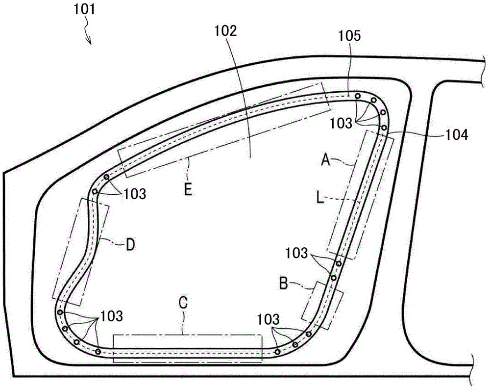
[0030] First, refer to figure 1 The seam welding method according to the first embodiment of the present invention will be described in detail.
[0031] The seam welding method of this embodiment, for example, in figure 1 The illustrated side panel 101 of an automobile is used as a workpiece when welding the peripheral edge of the door opening 102 of the side panel 101 . The side plate 101 is formed by laminating a plurality of metal plates, and the joint portion 103 is formed by performing spot welding at a plurality of places around the periphery of the door opening 102 to maintain the shape, and the plurality of metal plates are temporarily fixed by the joint portion 103 .
[0032] The seam welding method of the present embodiment is performed as follows: the regions A, B, C, D, and E between the joining parts 103 are used as welded parts, and the welded parts are clamped between a pair of rolling electrodes not shown in the figure. During this time, the rolling electrod...
no. 2 Embodiment approach
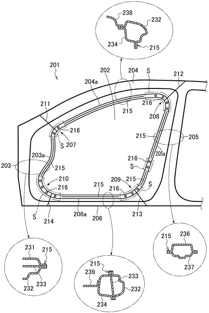
[0041] Next, refer to figure 2 A vehicle body according to a second embodiment of the present invention will be described in detail.
[0042] In this embodiment, the figure 2 The illustrated side panel 201 of an automobile is explained as an example of a vehicle body. A portion of a side panel 201 serving as a vehicle body surrounding the front door opening 202 is constituted by a front portion 203 , a front pillar 204 , a center pillar 205 , and a side sill 206 . The front door opening 202 has a substantially quadrangular shape, and portions of the quadrangular shape corresponding to the vertex corners form corners 207 , 208 , 209 , and 210 that form sharp curves.
[0043] The front part 203, the front pillar 204, the center pillar 205, and the side sill 206 are all formed by laminating parts obtained by stamping a plurality of sheet metal materials. The stacking state of the sheet metal, such as the number, material, sheet thickness, etc., varies. For example figure ...
PUM
 Abstract
Description
Claims
Application Information
 - R&D
- Intellectual Property
- Life Sciences
- Materials
- Tech Scout
- Unparalleled Data Quality
- Higher Quality Content
- 60% Fewer Hallucinations
Browse by: Latest US Patents, China's latest patents, Technical Efficacy Thesaurus, Application Domain, Technology Topic, Popular Technical Reports.
© 2025 PatSnap. All rights reserved.Legal|Privacy policy|Modern Slavery Act Transparency Statement|Sitemap|About US| Contact US: help@patsnap.com


