
Fixing and protecting device used when dust collector is transported

A technology for fixed protection and vacuum cleaners, which is applied in the direction of vacuum cleaners, cleaning equipment, household appliances, etc. It can solve the problems of brittle and easy to break protection pads, unable to support and protect vacuum cleaners, etc., and achieve the effect of reducing contact damage, avoiding damage, and increasing the contact area

Active Publication Date: 2016-03-09
NINGBO HAIJI ELECTRIC APPLIANCE
View PDF5 Cites 0 Cited by
  • Summary
  • Abstract
  • Description
  • Claims
  • Application Information

AI Technical Summary

Problems solved by technology

[0003] The disadvantage of the prior art is that the traveling wheels of the vacuum cleaner are usually used as a fulcrum in the packing box, and the traveling wheels are usually arranged at the rear of the vacuum cleaner. When the vacuum cleaner vibrates during transportation, due to the leverage generated by the position of the traveling wheels, The stress on the front of the vacuum cleaner mainly comes from its lower part, while the stress on the rear mainly comes from the lateral inertial force, and the protective pad made of foam material is brittle and easy to break, and cannot provide preset support for the vacuum cleaner after breaking Protect

Method used


Image

  • Fixing and protecting device used when dust collector is transported
  • Fixing and protecting device used when dust collector is transported
  • Fixing and protecting device used when dust collector is transported

Examples


Embodiment Construction

[0016] A specific embodiment of the present invention will be described in detail below in conjunction with the accompanying drawings, but it should be understood that the protection scope of the present invention is not limited by the specific embodiment.

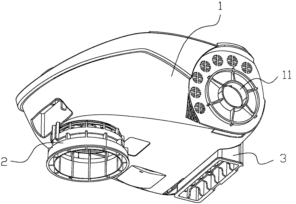
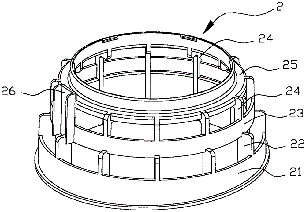
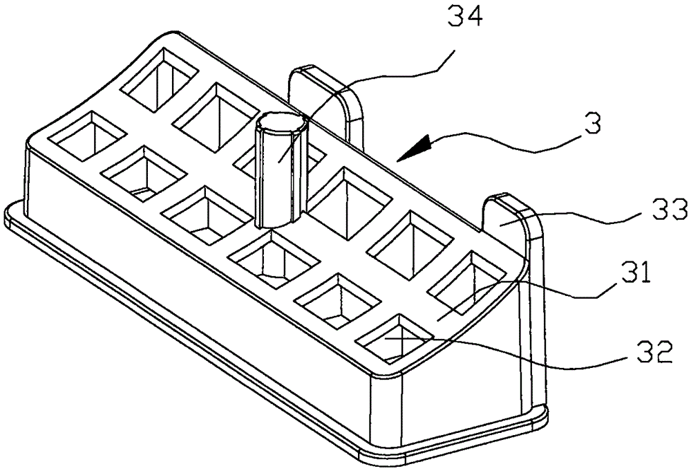
[0017] A fixed protection device for vacuum cleaner transportation according to the present invention is as follows: figure 1 , 2 , 3, including: a support ring 2 supporting the front portion of the vacuum cleaner 1 and a support base 3 supporting the rear portion of the vacuum cleaner, the rear portion of the vacuum cleaner 1 is provided with a shaft hole 11 for a traveling wheel, and the traveling wheel (not shown) is provided At the position corresponding to the shaft hole 11; the support ring 2 is made of elastic plastic integrally formed into a ring structure, consisting of three layers of rings connected axially by the bottom support ring 21, the middle support ring 23 and the upper support ring 25 , the bottom supp...


PUM


Abstract

The invention discloses a fixing and protecting device used when a dust collector is transported. The device comprises a supporting ring and a supporting base, the supporting ring supports the front portion of the dust collector, and the supporting base supports the rear portion of the dust collector. The supporting ring is of a ring structure and formed by axially connecting three layers of rings. The rings are connected through a plurality of supporting columns which are arranged around the rings at equal intervals. The diameters of the rings are gradually reduced from bottom to top. The end face of the uppermost layer of supporting ring is in butt joint with the bottom face of the front portion of the dust collector. The supporting base is a transverse columnar body, and the upper surface of the supporting base is an arc face and is in butt joint with the arc face at the corner between the lower surface of the rear portion of the dust collector and the rear wall of the dust collector. The supporting ring is arranged to be of a multi-layer structure so that the supporting ring can keep elastic axial deformation and can reliably support the bottom of the dust collector all the time, and damage caused when the front portion of the dust collector moves downwards due to transportation is avoided. Fixing columns arranged for the supporting rings can effectively constrain backward transverse moving of the dust collector during vibration, damage caused when the dust collector transversely moves backwards is avoided, and safety of the dust collector in the transportation process is guaranteed.

Description

technical field [0001] The invention relates to an auxiliary device of a vacuum cleaner, in particular to a fixing protection device for a vacuum cleaner during transportation. Background technique [0002] The existing vacuum cleaner needs to be provided with a foamed protective pad in the packaging box before transportation. The shape of the protective pad matches the shape of the bottom of the vacuum cleaner. When the packaging box vibrates, the protective pad forms a buffer protection for the vacuum cleaner. [0003] The disadvantage of the prior art is that the traveling wheels of the vacuum cleaner are usually used as a fulcrum in the packing box, and the traveling wheels are usually arranged at the rear of the vacuum cleaner. When the vacuum cleaner vibrates during transportation, due to the leverage generated by the position of the traveling wheels, The stress on the front of the vacuum cleaner mainly comes from its lower part, while the stress on the rear mainly com...

Claims


Application Information

Patent Timeline
Patent Type & Authority Applications(China)
IPC IPC(8): A47L9/00
Inventor 周荣
Owner NINGBO HAIJI ELECTRIC APPLIANCE
Learn More