A kind of protection device for top angle of shell structure

A technology of shell structure and protection device, which is applied in the direction of packaging, transportation and packaging, and containers to prevent mechanical damage. It can solve the problems of easy damage of rubber protective pads, easy falling off of protective pads, and failure of protection, etc., to protect the shell structure. The effect of top corner, good shell structure top corner, good cushioning force

Active Publication Date: 2017-09-19
重庆凯顺机械有限公司
View PDF5 Cites 4 Cited by
  • Summary
  • Abstract
  • Description
  • Claims
  • Application Information

AI Technical Summary

Problems solved by technology

[0002] The shell of mechanical equipment is prone to deformation under the action of external force. The protection method for the top corner of the shell of the mechanical structure is mainly to bond the rubber protection pad to the top corner. Because the rubber protection pad is easy to be damaged under the action of external force, resulting in The protection fails, and at the same time during the bonding process, if the external temperature of the shell is high, the bonding will not be firm and the protective pad will fall off easily

Method used


Image

  • A kind of protection device for top angle of shell structure

Examples


Embodiment 1

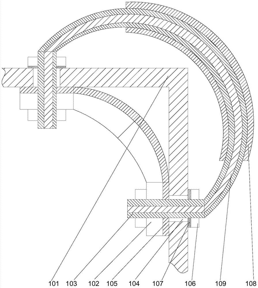
[0020] Such as figure 1 As shown, a shell structure corner protection device includes a support base 102 arranged inside the shell structure 101 and a support tube 103 set outside the shell structure 101, and the two ends of the support tube 103 are respectively located at the On the two side walls of the shell structure 101, the middle part of the support tube 103 is bent away from the support base 102 to form an arched structure, and two sets of through holes are arranged on the shell structure 101 The structure 104 is provided with external threads at both ends of the support pipe 103, and the two ends of the support pipe 103 pass through the through-hole structure 104 and are screwed on the ground support base 102. A cushion layer 105 is provided on the side of the base 102 facing the inner wall of the shell structure 101, and a lock nut 106 is set on the end of the support tube 103 close to the shell structure 101. 106 is provided with a rubber cushion 107 on the side fa...

Embodiment 2

[0023] In this embodiment, on the basis of Embodiment 1, in order to improve the impact resistance of the support tube, in this embodiment, preferably, an anti-skid rubber 108 is set in the middle of the support tube 103, and the outer wall of the anti-skid rubber 108 is There are anti-slip embossed on it. By setting anti-slip rubber and anti-slip embossed structure, the friction force between the support tube and the external structure can be increased, so that when it is impacted by an external force, it is not easy to drive the entire shell structure to tilt, which helps to improve the shell structure. structural stability.

[0024] Further preferably, in order to facilitate installation and prevent the anti-slip rubber from falling off at high temperature, in this embodiment, the inner wall of the anti-slip rubber 108 is coated with a high-temperature resistant resin adhesive, and the inner wall of the anti-slip rubber 108 passes through The high temperature resistant res...


PUM


Abstract

The invention discloses a housing structure top corner protecting device which comprises a support base arranged at the inner side of a housing structure and a support pipe arranged the outer side of the housing structure, wherein the two ends of the support pipe are positioned on the two side walls of the housing structure respectively; the middle of the support pipe is bent towards the direction far away from the support base to form an arch structure; two through hole structures are arranged on the housing structure; the two ends of the support pipe penetrate through the through hole structures and are in threaded connection with the support base; a cushion layer is arranged at one side, facing towards the inner wall of the housing structure, of the support base; locking nuts arranged at the ends, close to the housing structure, of the support pipe; and rubber cushions are arranged at the sides, facing towards the housing structure, of the locking nuts. With the adoption of the support pipe supporting the outer side of a top corner part of the housing structure, the support pipe exerts a cushioning effect when an external force impacts, and the top corner part of the housing structure is prevented from being damaged.

Description

technical field [0001] The invention relates to the field of shell processing of mechanical equipment, in particular to a top corner protection device for a shell structure. Background technique [0002] The shell of mechanical equipment is prone to deformation under the action of external force. The protection method for the top corner of the shell of the mechanical structure is mainly to bond the rubber protection pad to the top corner. Because the rubber protection pad is easy to be damaged under the action of external force, resulting in The protection fails, and at the same time during the bonding process, if the external temperature of the shell is high, the bonding will not be firm and the protective pad will easily fall off. Contents of the invention [0003] The purpose of the present invention is to provide a protective device for the top corner of the shell structure, which can improve the existing problems in time. By adopting the support tube structure to supp...

Claims


Application Information

Patent Timeline
Patent Type & Authority Patents(China)
IPC IPC(8): B65D81/05
CPCB65D81/054B65D2581/057
Inventor 万平
Owner 重庆凯顺机械有限公司
Why Eureka
Try Eureka