Spiral discharging device for dust collector

A technology of screw unloading and dust collector, applied in the field of unloading devices, can solve the problems of harsh on-site environment, increased material processing cost, inconvenient inspection and maintenance, etc., to improve the operating environment, facilitate inspection and maintenance, and reduce equipment maintenance. Effects of cost and workload

Inactive Publication Date: 2016-03-09
JINAN AOHAI CARBON PROD
View PDF6 Cites 5 Cited by
  • Summary
  • Abstract
  • Description
  • Claims
  • Application Information

AI Technical Summary

Problems solved by technology

[0002] At present, the spiral unloading device of the dust collector used in the workshop can not be lubricated due to the screw intermediate support bearing being set in a discharge shell, which causes dry friction. Often ground and leaked powder
It is necessary to frequently repair the discharge casing of the spiral discharge device of the dust collector, which increases the amount of maintenance, and at the same time increases the safety hazards caused by high-altitude operations and hot-fire operations. When the screw shaft is worn out to scrap, it must be Shutdown for maintenance, affecting output, increasing material and processing costs; powder leakage makes the site environment worse, affecting the health of operators; at the same time, the joints of the screw shaft of the dust collector screw discharge device are all in the shell, so there is no Easy inspection and maintenance

Method used


Image

  • Spiral discharging device for dust collector

Examples


Embodiment 1

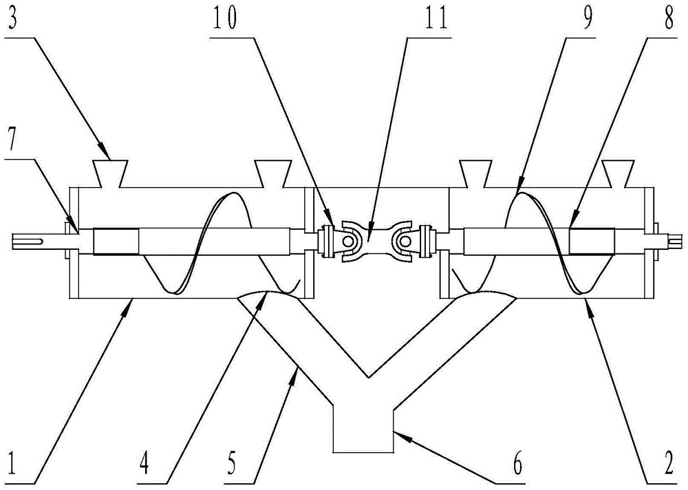
[0012] Such as figure 1 As shown, a dust collector spiral discharge device is characterized in that: the dust collector spiral discharge device has a first discharge housing 1 and a second discharge housing 2, the first discharge housing 1 and the second discharge shell 2 respectively have a cylinder and two opposite side plates sealing the cylinder. The tops of the first discharge shell 1 and the second discharge shell 2 are respectively arranged in sequence There are two feeding ports 3, and a discharging port 4 is respectively provided at the bottom. The discharging port 4 is sleeved with a powder output branch pipe 5. The first discharging shell 1 and the second discharging shell 2 barrel out The outlet 4 is sleeved and then the output end of the powder output branch pipe 5 is hermetically connected to the powder output pipe 6; the first discharge housing 1 and the second discharge housing 2 are also provided with powder conveying devices, respectively, The powder conveyin...

Embodiment 2

[0015] Such as figure 1 As shown, a dust collector spiral discharge device is characterized in that: the dust collector spiral discharge device has a first discharge housing 1 and a second discharge housing 2, the first discharge housing 1 and the second discharge shell 2 respectively have a cylinder and two opposite side plates sealing the cylinder. The tops of the first discharge shell 1 and the second discharge shell 2 are respectively arranged in sequence There are two feeding ports 3, and a discharging port 4 is respectively provided at the bottom. The discharging port 4 is sleeved with a powder output branch pipe 5. The first discharging shell 1 and the second discharging shell 2 barrel out The outlet 4 is sleeved and then the output end of the powder output branch pipe 5 is hermetically connected to the powder output pipe 6; the first discharge housing 1 and the second discharge housing 2 are also provided with powder conveying devices, respectively, The powder conveyin...


PUM


Abstract

The invention discloses a spiral discharging device for a dust collector. The spiral discharging device for the dust collector is provided with a first discharging shell and a second discharging shell. Dust conveying devices are further arranged in the first discharging shell and the second discharging shell respectively. Each dust conveying device comprises a spiral shaft and a spiral fixedly connected to the spiral shaft. The ends, stretching out of two adjacent side plates, of the spiral shafts installed on bearing seats on the side plates of the first discharging shell and the second discharging shell are connected with a universal rotary shaft through universal rotary shaft connecting flanges respectively. According to the spiral discharging device for the dust collector, the phenomenon that the discharging shells are swept and abraded due to falling and bending of the spiral shafts, and consequently dust leakage is caused is prevented, and checking and maintenance of the spiral shafts are facilitated; the field operating environment is improved, the equipment maintenance cost and workload are reduced, and continuous and stable operation of the spiral discharging device for the dust collector is achieved.

Description

Technical field [0001] The invention belongs to a discharge device for a dust collector, in particular to a spiral discharge device for a dust collector. Background technique [0002] At present, the spiral discharge device of the dust collector used in the workshop causes dry friction because the spiral intermediate support bearing is installed in a discharge shell and cannot be lubricated. The spiral shaft is ground and falls and bends and deforms, which results in sweeping, resulting in the discharge shell. Often leaked powder. It is necessary to frequently weld and repair the discharge shell of the spiral discharge device of the dust collector, which increases the amount of maintenance, and at the same time increases the safety hazards caused by high-altitude operations and hot operations. When the screw shaft is worn to the scrap, it is necessary Shutdown for maintenance will affect the output, increase the cost of materials and processing; the phenomenon of powder leakage ...

Claims


Application Information

Patent Timeline
Patent Type & Authority Applications(China)
IPC IPC(8): B65G33/14B65G33/32
CPCB65G33/14B65G33/32B65G2201/042
Inventor 赵庆才尹燕岱陈光超刘大伟黄英来孙宗强翟美于磊张国
Owner JINAN AOHAI CARBON PROD
Why Eureka
Try Eureka