Special lifting anti-falling machine for three-dimensional centered steel single-guide-rail and double-screw attached scaffold

A technology of double screw rod and single guide rail is applied in the direction of scaffolding supported by housing structure, housing structure support, housing structure support, etc., which can solve the problems of difficult disassembly, high cost and complex structure.

Active Publication Date: 2016-03-09
胡泽矩 +1
View PDF6 Cites 0 Cited by
  • Summary
  • Abstract
  • Description
  • Claims
  • Application Information

AI Technical Summary

Problems solved by technology

[0007] The technical problem to be solved by the present invention is to provide a safe, reliable, easy to disassemble, reasonable in structure and low in cost for the problems of traditional attached scaffold lifting device, such as complicated structure, difficult disassembly and assembly, high cost and poor safety. Medium-sized steel single guide rail double screw rod attached scaffolding special lifting anti-fall machine

Method used


Image

  • Special lifting anti-falling machine for three-dimensional centered steel single-guide-rail and double-screw attached scaffold
  • Special lifting anti-falling machine for three-dimensional centered steel single-guide-rail and double-screw attached scaffold
  • Special lifting anti-falling machine for three-dimensional centered steel single-guide-rail and double-screw attached scaffold

Examples


Embodiment

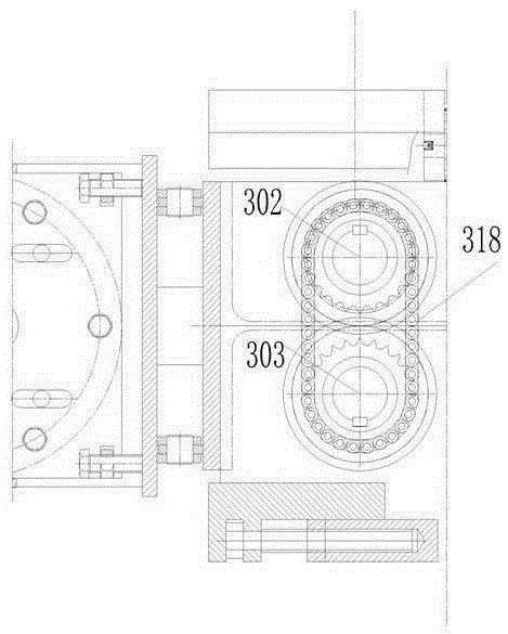
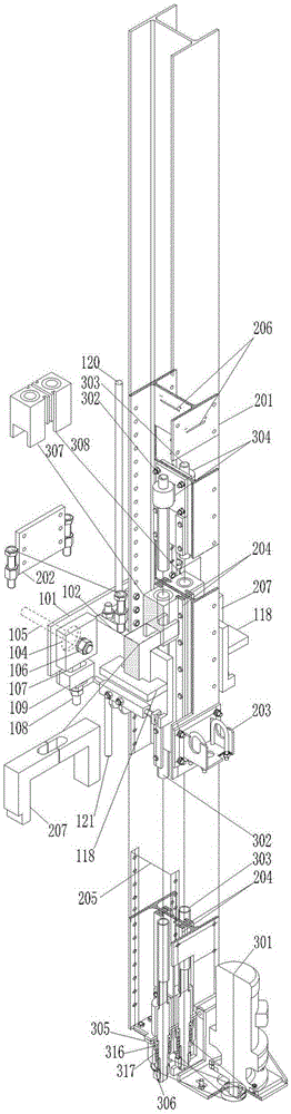
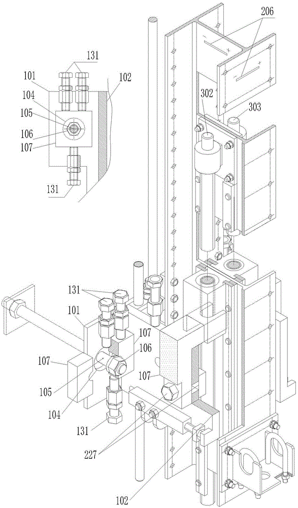
[0054] Example: Such as Figure 1 to Figure 20 As shown, the three-dimensional centered steel single guide rail double screw rod attached scaffolding special lifting anti-falling machine of the present invention is equipped with a three-dimensional deviation correction centering interconnection wall support device, a steel single track deflection warning device and double screw rods in the track. Composed of spiral lifting and anti-falling devices; three-dimensional correction centering installation interconnection wall support device consists of wall-mounted plate 101, cantilever plate 102, horizontal plate 103, wall-through bolt 105, wall-through bolt nut 106, wall-through bolt nut Large backing plate 107, backing plate bolt 108, rectangular pipe seat 109, guide wheel 112, helical distance adjustment slider 113, anti-overturning roller 114, anti-overturning roller stepped shaft 115, pin seat 118, upper connecting twin screws 120, lower connecting Composed of double screw r...


PUM


Abstract

The invention relates to a special lifting anti-falling machine for a three-dimensional centered steel single-guide-rail and double-screw attached scaffold. The special lifting anti-falling machine for the three-dimensional centered steel single-guide-rail and double-screw attached scaffold comprises a three-dimensional deviation-rectifying and centering mounting interconnected wall-attached support device, a hot-rolled steel single guide rail and a double screw spiral lifting anti-falling device, wherein the hot-rolled steel single guide rail is provided with a deviation warning indicator; and the double screw spiral lifting anti-falling device is placed in the rail. Through the adoption of the three-dimensional deviation-rectifying and centering mounting interconnected wall-attached support device, position deviation of a wall bolt embedded pipe is overcome so that a plurality of supports mutually support the load of the scaffold to effectively prevent safety problems caused by bending of the guide rail and the structural deformation of the scaffold. As the guide rail is lifted by using a screw spiral transmission method, a screw spiral transmission self-locking function is adopted as a safety device, the double-screw spiral structure is concealed in the hot-rolled steel single guide rail and a nut slide way is made by using the inner wall of a profile steel, the special lifting anti-falling machine is beneficial for screw protection. The hot-rolled steel single guide rail with the deviation warning indicator is mounted to match the three-dimensional centering support; and cams at the bottom ends of screws control the screws in the same lifting unit to rotate one more circle after the screws in the same lifting unit both rotate for one circle so that the lifting height difference of the guide rail is controlled within a screw pitch.

Description

technical field [0001] The invention relates to the technical field of building construction machinery, in particular to a three-dimensional centering steel single guide rail double screw rod attached scaffolding special lifting and anti-falling machine. Background technique [0002] Scaffolding is an indispensable kind of machinery in construction engineering. With the development of the construction industry, many changes have taken place in scaffolding. At present, most of them are attached lifting scaffolding. Since the lifting mechanism of scaffolding needs to be attached to the wall, it is necessary to Bolts are installed on the wall, but because the bolts cannot be installed at the designated positions, it is difficult to install the track according to the requirements. If the installation position of the bolts deviates too much, it will make the installation of the lifting mechanism very difficult, and the track is easy to bend during use. , Major accidents are prone...

Claims


Application Information

Patent Timeline
Patent Type & Authority Applications(China)
IPC IPC(8): E04G3/32
Inventor 胡泽榘胡川
Owner 胡泽矩
Why Eureka
Try Eureka