
Cooling suite of LED project lamp

A technology for LED flood light and flood light, which is applied to semiconductor devices of light-emitting elements, parts of lighting devices, cooling/heating devices of lighting devices, etc. Complicated and other problems, to achieve the effect of beautiful and tidy appearance, remarkable heat dissipation effect, and overall smooth and uniform effect

Active Publication Date: 2016-03-09
中山市国丰光电科技有限公司
View PDF6 Cites 2 Cited by
  • Summary
  • Abstract
  • Description
  • Claims
  • Application Information

AI Technical Summary

Problems solved by technology

Therefore, the reduction of temperature is mainly related to the thermal convection effect. In order to maximize the thermal convection effect, the radiator itself must have the largest heat dissipation area. The existing ones are often simple heat dissipation fin modules to increase heat dissipation. area, the heat dissipation fin module includes several heat dissipation fins and the bottom plate, and the connection method between the heat dissipation fins and the bottom plate is generally welding. It is rigid, and it is difficult to maximize the number of heat dissipation fins welded on the bottom plate, and the unevenness of the welding place affects the overall aesthetics. At the same time, only using heat dissipation fin modules to dissipate heat is far from satisfying LED floodlights. A large amount of heat cannot be dissipated quickly and effectively, which will affect the lighting effect of the LED floodlight and accelerate the light decay speed of the LED chip, shortening the service life

Method used


Image

  • Cooling suite of LED project lamp
  • Cooling suite of LED project lamp
  • Cooling suite of LED project lamp

Examples


Embodiment Construction

[0021] It should be understood that the specific embodiments described here are only used to explain the present invention, not to limit the present invention.

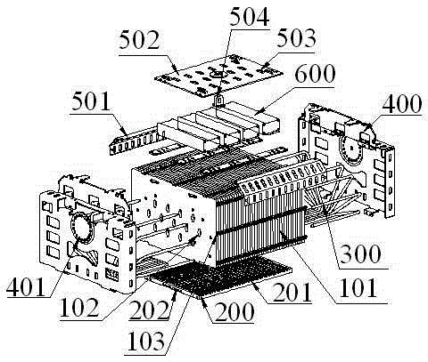
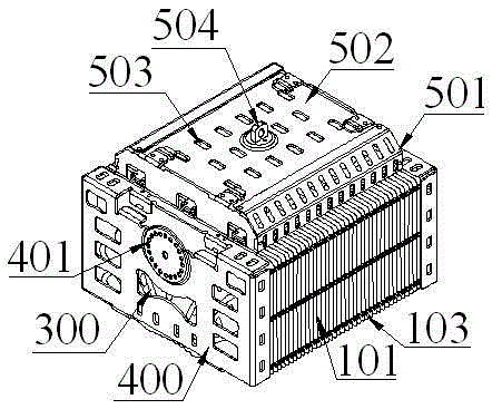
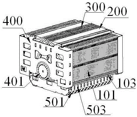
[0022] refer to Figure 1 to Figure 6 , an embodiment of the heat dissipation kit of the LED floodlight of the present invention is proposed, which can be fixedly connected with the LED illuminant, including a heat dissipation module and a driving device 600 fixed on the heat dissipation module and electrically connected to the LED illuminant. The illuminant is fixed on the lower end surface of the heat dissipation module.

[0023] The heat dissipation module includes a heat dissipation fin module, a metal heat conduction plate 200, a number of heat pipes 300 embedded in the metal heat conduction plate 200 and interspersed in the heat dissipation fin module with superconducting heat capacity, and located on the heat dissipation fin module. The mounting side plates 400 on both sides and protecting the heat pipe 300 , ...


PUM


Abstract

The invention discloses a cooling suite of an LED project lamp. The cooling suite can be fixedly connected with an LED light emitting body and comprises a cooling module and a driving device. Cooling fins of the cooling suite are arranged at equal intervals through buckle FINs and connected tightly in a buckled mode. Connection is flat, the appearance is attractive, the buckling strength is high, the cooling area can be maximized, and the cooling effect is ideal. The cooling fins are tightly and fixedly attached to a metal heat conductive plate through the punching effect of a punch, and the technology is simple. A plurality of heat pipes with the super heat conduction function are fixedly embedded to the metal heat conductive plate. The heat pipes are inserted into the cooling fin module, and the cooling fin module is tightly attached to the heat pipes through the punching effect of the punch. The LED light emitting body is tightly attached to the heat pipes, the heat pipes have the super high heat conductivity, heat produced by the LED light emitting body can be rapidly absorbed and rapidly transmitted to the cooling fin module, the cooling fin module is perfectly combined with the heat pipes, the heat conductivity is super strong, the cooling effect is significant, normal use of the LED light emitting body is effectively ensured, and the service life of the LED project lamp is prolonged.

Description

technical field [0001] The invention relates to the field of heat dissipation devices, in particular to heat dissipation kits for LED floodlights. Background technique [0002] Energy and the environment are major challenges faced by human beings in the 21st century, so green energy conservation has become the focus of world attention. With its high efficiency and energy-saving characteristics, LED has gained unprecedented opportunities in the field of lighting, especially with the improvement of LED chip technology, the reduction of price and the maturity of related driving circuits, LED lamps have been widely used in the field of lighting, especially high-power LED floodlights. [0003] However, the chip of the high-power LED floodlight itself will generate a lot of heat when it is working. If the heat dissipation performance of the LED floodlight is poor, the heat will not be dissipated quickly, which will have a great impact on its luminous effect and service life. . ...

Claims


Application Information

Patent Timeline
Patent Type & Authority Applications(China)
IPC IPC(8): F21V29/76F21V29/51F21V29/71F21V17/10F21Y115/10
CPCF21V17/10
Inventor 刘树泽
Owner 中山市国丰光电科技有限公司
Learn More