
Direct-current wind tunnel device and working method thereof

A wind tunnel and airflow technology, applied in the direction of measuring devices, instruments, aerodynamic tests, etc., can solve the problems of high equipment requirements, short explosion time, and large power grid pressure, and achieve the effect of simplified wind tunnel structure and high efficiency

Inactive Publication Date: 2016-03-09
苟仲武
View PDF6 Cites 2 Cited by
  • Summary
  • Abstract
  • Description
  • Claims
  • Application Information

AI Technical Summary

Problems solved by technology

[0002] At present, DC wind tunnels generally adopt the existing method of using high-speed fans and large fans. When starting the wind tunnel, the power consumption is huge, ranging from tens of kilowatts to tens of thousands of kilowatts, and it is difficult to reach supersonic speed. Higher, an unstable large load puts a lot of pressure on the power grid; another is to use explosion to generate airflow, but the explosion time is relatively short, the time is about 0.1 to 2 seconds, and the required equipment requirements are also relatively high; the third The first is to use high-pressure gas cylinders to store a large amount of gas to generate short-time pulsed high-speed airflow, but it cannot meet the existing requirements

Method used


Image

  • Direct-current wind tunnel device and working method thereof
  • Direct-current wind tunnel device and working method thereof

Examples


Embodiment Construction

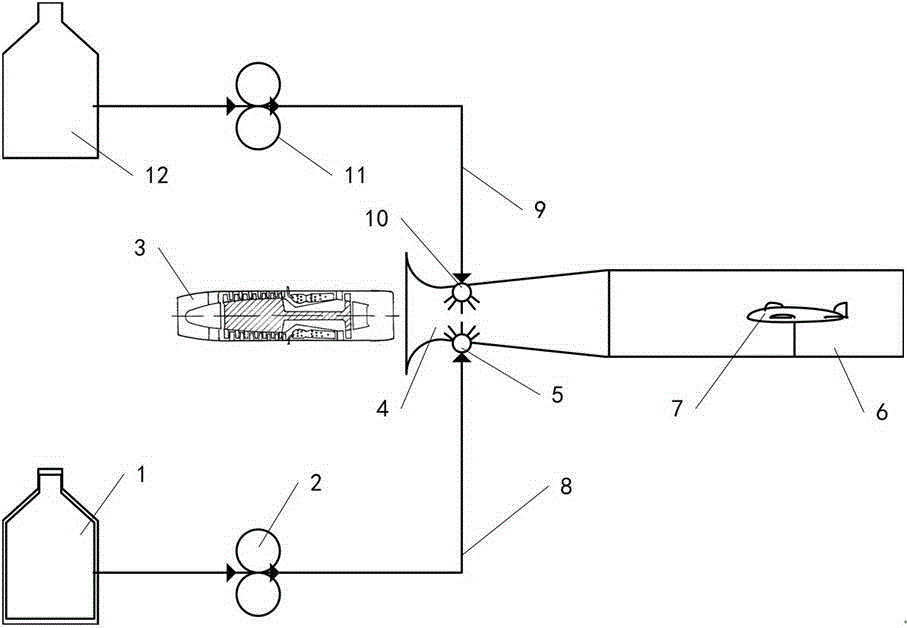
[0018] In this example, refer to Figure 1 to Figure 2 As shown, a DC wind tunnel device includes a liquid air storage tank 1, a cryopump 2 connected to the liquid air storage tank 1, a liquid air pipeline 8 connected to the cryopump 2, and a liquid air pipeline 8 The connected liquid air atomizing nozzle 5, and the water atomizing nozzle 10 arranged on one side of the liquid air atomizing nozzle 5, and the water pipeline 9 connected with the water atomizing nozzle 10, and the liquid pump 11 connected with the water pipeline 9 , and the water storage tank 12 that is connected with the liquid pump 11, and the mixing stabilization section 4 fixed on one end of the liquid air atomizing nozzle 5 and the water atomizing nozzle 10, and the other with the liquid air atomizing nozzle 5 and the water atomizing nozzle 10 The test section 6 connected at one end, the test model 7 arranged in the test section 6, and the jet engine 3 arranged on one side of the mixing and stabilizing sectio...


PUM


Abstract

The invention discloses a direct-current wind tunnel device and a working method thereof. The direct-current wind tunnel device comprises a liquid air storage tank, a cryopump, a liquid air pipeline, a liquid air atomization nozzle, a water atomization nozzle, a water pipeline, a liquid pump, a water storage tank, a mixing stable segment, a test segment, a test model and a jet engine. According to the invention, a jet engine technology is adopted, a high-temperature high-speed air flow is directly generated, the air flow is mixed with liquid air, and the liquid air absorbs heat to be gasified; in addition, according to different jet temperatures of the engine and the amount change of mixed liquid air, air flows from -140 to +500 DEG C and from 0 to 500 m / s can be obtained, so that the working requirements are met.

Description

technical field [0001] The invention relates to a direct current wind tunnel device, in particular to a direct current wind tunnel device and a working method thereof. Background technique [0002] At present, DC wind tunnels generally adopt the existing method of using high-speed fans and large fans. When starting the wind tunnel, the power consumption is huge, ranging from tens of kilowatts to tens of thousands of kilowatts, and it is difficult to reach supersonic speed. The power supply requirements Higher, an unstable large load puts a lot of pressure on the power grid; another is to use explosion to generate airflow, but the explosion time is relatively short, the time is about 0.1 to 2 seconds, and the required equipment requirements are also relatively high; the third One is to utilize high-pressure gas cylinders to store a large amount of gas earlier to generate short-time pulse high-speed airflow, but it cannot meet the existing requirements. Contents of the inven...

Claims


Application Information

Patent Timeline
Patent Type & Authority Applications(China)
IPC IPC(8): G01M9/02
CPCG01M9/02
Inventor 苟仲武
Owner 苟仲武
Learn More